Showing posts with label Adaptor. Show all posts

Tuesday, 28 April 2020

Moog Voyager XV-351 Output Adaptor

If you have a Moog Voyager (the backlit version, not the Old School or RME versions) and you want to connect a VX-351 Output Expander you need to have an Output Adaptor fitted to the output ribbon cable connection on the Voyager's analogue board. The trouble is that Moog no longer provide these and if you have bought a VX-351 for your Voyager and the VX-351 seems to be misbehaving (CV instability or noise) then the chances are you don't have an adaptor fitted.

A few years ago I set out to design a eurorack module that did much of what the VX-351 does i.e. output all the Voyager's internal signals (CVs and gates) but to make them a little more eurorack friendly and add a few twists: red and white noise, random gate pulses, more LFO wave shapes and variable slew. The result was the VXP1 (you can read all about the VXP1 here). 

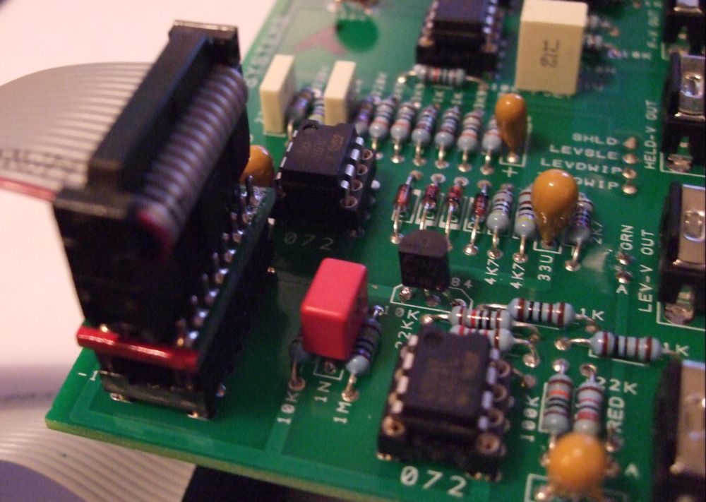
I also could not get VX-351 Output Adaptors to sell as part of the VXP1 package so I designed my own version from scratch to be a 'form-fit-function' replacement. I use it with both my VXP1 and VX-351 and it works a treat!

VXP1 Output Adaptor

To be clear you do not need this if you want to use a VX-351 (or VXP1 for that matter) with Old School or RME Voyagers.

Check out this useful 3rd party web page which describes how to open the Voyager and fit the Output Adaptor .


Sunday, 10 April 2016

VXP1 Voyager Output Expander for Eurorack

(BLOG UPDATED 3rd August 2018)

News


VXP1 and VXP1-OS are no longer available from Synovatron for £180.00 GBP. 

Preliminary user manuals can be downloaded from these links:
VXP1 Handbook Rev 1.0 
VXP1-OS Hand Book Rev1.3

Back Story

A few years ago I designed and built a Eurorack interface for my Moog Voyager. I built it in a week to take to the Brighton Modular meet to see if there was any interest in such a module.

I have a Moog VX-351 which is a perfectly lovely bit of kit but I wanted something that had 3.5mm minijacks to make it easier to use with my Eurorack and Roland 100m modulars. The module I built was a simple breakout panel that had one jack per signal available on the Voyager's Accessory Port (a 25 pin D connector). Most signals were wired straight through but one or two included active electronics to provide scaling to give a more useful 5V range, in particular Keyboard Pitch had a scaling amplifier and a trimmer to set it exactly to 1V/octave. LEDs with driver circuits were also added to the LFO and the two gate signals.


Prototype Voyager Output Expander

Most modular users don't have a Voyager (and sadly it's now out of production) so I didn't get too much interest at the Brighton meet but I did get some interest on Twitter and Muffwiggler and in particular from one wiggler whose frequent enquiries about its development has spurred me on to develop it. It has been very slow going due to a number of reasons (not all connected to the module itself, the real world has a way of changing one's focus!).

Output Adaptor Retrofit

One reason for procrastination was due to an error in Moog's design of the Voyager's Accessory Port which was not suitably buffered; which means that when a cable is connected to the port some of the signals become unstable and oscillate. Moog's remedy for this was to use a small adaptor board that has to be retrofitted inside the Voyager between the main circuit board and the Accessory Port's ribbon cable (this just affects backlit types, not the Old School version).

The Output Adaptor is a small circuit board that adds a 330 Ohm resistor in series with many of the signals; here is a link to an installation guide. The 330 Ohm resistance is enough to isolate the capacitance of the extra cable length which maintains amplifier stability (ED Note: If you want to understand about amplifier stability then this series of 5 short videos by Analogue Devices is the perfect intro, in particular video 4 which describes this problem nicely. Ideal for anyone designing with op-amps).

As you will see from the installation guide that fitting the adaptor is a bit much for some people to take on and I didn't want to encourage inexperienced Voyager owners to open up their expensive synth and potentially damage it or harm themselves (there is an AC mains hazard around the power inlet if you don't disconnect from the mains). Unfortunately there is no other solution other than to use an Output Adaptor (like that supplied with the VX-351) so fit it if you are confident or get a music shop tech to fit it for you. You might already have one fitted if your Voyager has been used with the Moog VX-351. I tried to find a source of Moog Output Adaptors but alas no joy so I designed one from scratch; problem solved! Here it is:


Smaller, Better

Another reason for delay is that I increased the scope of what the VXP1 can do; I didn't want this to be a Eurorack rip-off of the VX-351. Rather than just a simple breakout panel it now handles each signal with active electronics as follows:
  • All signals are filtered, buffered and have the necessary gain and drive to give more Eurorack-friendly output levels.
  • The smooth and step Sample and Hold outputs are replaced by just one output and a variable control to give an adjustable slew to Sample and Hold.
  • There are more LFO waveforms: ramp, saw and 10V clock.
  • There are more noise options: white, red and random pulses.
  • The panel is narrower than the first prototype: 16HP down to 14HP.
Here is the second prototype panel I have used during my development (a simple but mechanically accurate panel with engraved text made by Schaeffer):


Here is the panel design:


For Old School Voyagers which don't have a touch panel the VXP1-OS has repurposed the redundant TOUCH sockets to become a 3-input gate combiner. 


VXP1 Module, Cable and Adaptor | VXP1-OS Front Panel


Friday, 22 May 2015

Synovatron Documents Downloads

EDIT 31May 2015:

For those who have tried to download from links printed on kits, fliers and data sheets etc without success: I apologise but the original file hosting site has shut down without warning in recent weeks. All Synovatron docs have now been rehosted onto Google Docs where they can be viewed or downloaded. The new links are shown on the Support tab above where all downloadable documents will be maintained from now on - if you experience any problems with file downloads please email me at synovatron@btinternet.com. Keep an eye out for new and updated documents. Any additions or significant updates will be announced on the blog as they occur.

The documents added to Google Docs are:-

CV Tools User Manual 
CVGT1 User Manual 
cvgtMM User Manual 
GTPulse Data Pack 
ASM2DB Adaptor Fitting Instructions & uZeus Tech Note 
DM2ASB Adaptor Fitting Instructions 
5ASM2DB Adaptor/Expander Bare Board Data Sheet and Fitting Instructions

Saturday, 13 September 2014

5 into 1 Analogue Systems to Doepfer Bus Adaptor/Expander

The new 5ASM2DB Analogue Systems Module to Doepfer A-100 Bus Adaptor/Expander is now in stock and available to order. 

SchneidersLaden have stock of 5ASM2DB which can be ordered from their website at http://www.schneidersladen.de/en/manufacturer/synovatron.html.

For DIY enthusiasts it is also available as a kit or as a bare PCB direct from Synovatron (please email synovatron@btinternet.com). 

The 5ASM2DB offers five Analogue Systems sockets on one small circuit board with low-current LED indicators to show that ±12V and +5V power is available. It comes with a ribbon cable to connect to the A-100 bus and four self-adhesive nylon PCB mounting pillars (you can of course use screwed in pillars so a drilling template will be provided).

If you have several Analogue Systems modules in a Euro rack then the 5ASM2DB could be a better alternative to using several ASM2DB Adaptors because it expands the bus and frees up A-100 Bus connectors for Euro modules; it costs roughly the same as three ASM2DB Adaptors. ASM2DB and DM2ASB Adaptors are still available.

5ASM2DB Adaptor/Expander
5ASM2DB DIY Kit

Friday, 29 August 2014

New product preview

This is a design that has been hanging around for over a year in a 95% complete state but I have now taken the bold step of finishing it and going into production. It is called the 5ASM2DB and is a 5 socket version of the popular ASM2DB Analogue Systems module to Doepfer bus Adaptor. It is fabricated on a small circuit board and has 3 LEDs that indicate the presence of ±12V and +5V. The 5ASM2DB will be supplied with 4 self-adhesive nylon mounting pillars and a short ribbon cable so it can be placed adjacent to a busboard and linked via the ribbon cable (standard Euro rack 16 pin cable). It is not recommended for use with the Analogue Systems RS-370 as this draws a whoppng 680mA from the 5V rail.

It will be priced at roughly that of 3 ASM2DB Adaptors so the aim is you get 5 for the price of 3; which will be of interest to those of you with many Analogue Systems modules to go in a Eurorack case.

Availability is from mid-September and will also be available as a DIY kit and as a bare PCB for the more adventurous DIYers. Here's an image from the CAD package - it will not be red BTW!


Friday, 22 April 2011

DIY Adaptor/Multiple Panel for scope and DMM connections

This is an adaptor panel I put together in an hour or two to help with testing and setting up the CV Tools Modules. 


I used one of my 8HP DIY panels and  DIY kit 3 for the 3.5mm jacks. 

It is essentially an adaptor and multiple to allow easy connection to the scope via BNC connectors and to a DMM (digital multimeter) via the 4mm sockets. 

The top 3.5mm jack and BNC socket are connected together, the next jack down and BNC are similarly connected; i.e. a pair of 3.5mm jack to BNC adaptors. The lower pair of 3.5mm jacks. 1/4" jack, BNC and red 4mm socket are all connected together and the black 4mm socket is connected to 0V.

This is really useful for DIY applications too and very easy to make. I think an adaptor or multiple panel would make a great first DIY project.


I can also make these to order if anyone wants one (or something similar) but it is unlikely to become a standard product as all you really need is a pre-drilled front-panel and a few connectors.
Here it is (bottom right) in use in my CV Tools test rig routing the scope, DMM and sig gen to the module under test

Tuesday, 25 January 2011

Analogue Systems to Doepfer Reverse Adaptor

Here is the prototype of the Analogue Systems to Doepfer Adaptor variant that I promised a few days back (The production version is now available. Edit Jan 2012) The adaptor uses a 16 way DIL turned-pin IC socket on one side and a PCB mount header socket on the other side; the version shown below is just a prototype using a cut-down header socket, it's a bit rough but demonstrates the principle - which is it allows you to use an Analogue Systems module with its cable in a Doepfer rack.


AS ribbon cable connector - note the red stripe at pin 1 (top) end
Here you can see the pin 1 and TOP markings

Doepfer bus board connector

Adaptor fitted to my AS RS-35 Module - note the red stripe at the top

The order code for the socket-to-socket version (above) is ASM2DB Adaptor (or Analogue Systems Module to Doepfer Bus Adaptor). The code for the plug-to-plug version is DM2ASB Adaptor (or Doepfer Module to Analogue Systems Bus Adaptor). The product page has been updated showing the production versions available for sale. 

Wednesday, 19 January 2011

Analogue Systems to Doepfer Adaptor

Hi all and a very happy new year to you all, I've been a bit slow with my first 2011 posting but have been busy.

I saw two enquiries on the Analogue Systems/Doepfer forums for adaptors to enable Doepfer modules to be used in old-style AS racks which are those with just 16-way dual in-line IC sockets; the newer types also have a few Doepfer header connectors. It seemed that the usual sources had dried up so I did some checking to see how this had been addressed in the past.  

There were two approaches; the first was to use a very messy ribbon cable adaptor that is not 1:1 which must have been nightmare to assemble, the other was a small PCB which allowed a Doepfer ribbon cable to mate with an Analogue Systems ribbon cable and this, I thought, was a bit awkward especially as it just sits anywhere in the rack with bare contacts that could easily short out on the metalwork.

I set about designing a solution which I think is really neat, onubtrusive and quite versatile. Here it is; this is the first build of a 100 PCBs and already have orders for 12 of them. Note the red stripe - just line up the Doepfer cable's red stripe with it.  The adaptor is also marked with pin 1 and an orientation mark so pin 1 goes to the top (in fact to pin 1) and the red stripe goes at the bottom - SIMPLE!


The above adaptor is barely bigger than the IC socket and allows you to do the following:-

  1. Use a Doepfer module and ribbon cable in an AS rack - it plugs into the AS bus board.
  2. Use an AS module and Doepfer cable in a Doepfer rack - it plugs into the AS module socket.

Here is the adaptor plugged into an AS module and below a Doepfer cable is fitted to the adaptor.  This is my only AS module and it's the RS-35 External Interface which has two connectors and the top one doesn't really have enough clearance to fit a standard vertical header so it's probably not the best example but never fear.  As far as having two connectors goes it's simple to fit two Doepfer headers at one end of a ribbon cable (which I will gladly supply) and the adaptor can be made with a right-angle header so it doesn't protrude too high (again I will gladly supply those too - this will all be posted up on my Products page in a jiffy).


Not groundbreaking, not rocket-science just a bit of thought and careful design and in case you are wondering yes it does translate the connections so that all the supplies are in the right place.

In a few more days I'll also have a variant that will plug into a Doepfer bus board to give you AS sockets so you can just keep the ribbon cables you have already.

Please note that Doepfer and Analogue Systems are registered trademarks and that Synovatron is not affiliated with, or endorsed by, either company.