Showing posts with label eurorack. Show all posts

Friday, 3 August 2018

Modules and Kits from Synovatron

Updated 31st January 2021: Synovatron will cease to trade from 1st February 2021 onwards. The following products will no longer be available from Synovatron Limited. Some items will be available from retailers and I will post the status of those when I know the final state:

CVGT1 - 8HP Euro to Buchla CV-gate-trigger-pulse translator
No longer available directly - please check out Noisebug or SchneidersLaden who have may stock of modules.

VXP1 - 14HP Voyager Output Expander
No longer available

VXP1-OS - 14HP Old School Voyager Output Expander
No longer available

Jacks - 4HP 3.5mm minijack to 1/4" jack format jumber
No longer available directly - this may become available for sale by another company - watch this space, I will update when I know

Euro Bananas - 6HP 3.5mm minijack to 4mm banana socket format jumbler
No longer available directly - this may become available for sale by another company - watch this space, I will update when I know

Trunks & Mults - 6HP 8-channel trunk lines and two 4-way multiples
No longer available directly - this may become available for sale by another company - watch this space, I will update when I know

More info on Jacks, Euro Bananas and Trunks & Mults modules and kits on this page.  


Euro Bananas, a pair of Trunks & Mults, Jacks, CVGT1 and VXP1


Limited edition Black Gold CVGT1 (SOLD)

Saturday, 13 June 2015

New Euro to Buchla CV Translator - CV1.2

The CV1.2, one of the cvgtElements range of DIY circuits, is available and its data pack is ready to view/download on the support page. CV1.2 is ready built and tested, you have to DIY them into your own modules/panels.

CV1.2 takes a Euro 1V/octave CV and translates it into a Buchla 1.2V/octave CV - ideal if you want to take a Euro pitch CV into the Music Easel's pitch KEYBOARD CONNECTION


The GTPulse datapack is also available to view/download on the support page.

Saturday, 8 November 2014

Custom Half-width Buchla Modules

I was asked to design and build a pair of custom half-width Buchla modules for some clients. They each had two half-width slots spare in their custom built cases and wanted to fill the spaces with Euro to Buchla CV and gate translator modules.


The brief was simple (and the same for both clients): 5 channels of 1V/oct to 1.2V/oct CV translation and 5 channels of gate boosting to Buchla levels; the Buchla stepped pulse was not required, just big pulses (10V or more).

This was a great opportunity to use the Synovatron Proto range of prototyping boards which accomodate 5 channels and offer stackability if more circuitry is required than will fit on one board; see below.

The Proto range of boards
As the Proto boards are designed primarily for Euro there was space on the 4U Buchla front panels to add some extras in the form of a passive attenuator. Here are the front panel designs that we agreed on:-

CV and Gate modules
To keep costs down it was decided not to have panel marking as the functions are obvious.

The CV module design used a straightforward precision amplifier with gain of 1.2000 (yes that accurate), 1M Ohm input and 0 Ohm output impedances. The gate module used comparators and output and LED drivers. The outputs each have diodes in series allowing them to be wire-ORed by just connecting outputs together (common to Buchla, wish it was used on Euro).

The CV module electronics fitted nicely on a ProtoJax board with plenty of space as you can see:-


For the gate module I decided to put the input comparators and sockets on the ProtoJax board and output buffers and LEDs on the ProtoXp board and stack them together (it  probably could all have been put on one board but it was simpler to make use of the space). The stacked ProtoJax and ProtoXp boards can be seen here:-


The gate board was powered from an MTA connector and the CV board took its power from the gate module (hence the 10-pin ribbon headers for a linking ribbon cable); this was at the client's request as they only had one spare connector (these are very low current modules and daisy chaining them didn't cause any crosstalk issues). 

The finished panels looked pretty good; they were made by Schaeffer using Front Panel Designer http://www.schaeffer-ag.de/en/front_panel_designer/the_idea/.

  
If you are interested in the Proto range of PCBs or in having a custom module built then please contact me at synovatron@btinternet.com


Saturday, 13 September 2014

5 into 1 Analogue Systems to Doepfer Bus Adaptor/Expander

The new 5ASM2DB Analogue Systems Module to Doepfer A-100 Bus Adaptor/Expander is now in stock and available to order. 

SchneidersLaden have stock of 5ASM2DB which can be ordered from their website at http://www.schneidersladen.de/en/manufacturer/synovatron.html.

For DIY enthusiasts it is also available as a kit or as a bare PCB direct from Synovatron (please email synovatron@btinternet.com). 

The 5ASM2DB offers five Analogue Systems sockets on one small circuit board with low-current LED indicators to show that ±12V and +5V power is available. It comes with a ribbon cable to connect to the A-100 bus and four self-adhesive nylon PCB mounting pillars (you can of course use screwed in pillars so a drilling template will be provided).

If you have several Analogue Systems modules in a Euro rack then the 5ASM2DB could be a better alternative to using several ASM2DB Adaptors because it expands the bus and frees up A-100 Bus connectors for Euro modules; it costs roughly the same as three ASM2DB Adaptors. ASM2DB and DM2ASB Adaptors are still available.

5ASM2DB Adaptor/Expander
5ASM2DB DIY Kit

Friday, 29 August 2014

New product preview

This is a design that has been hanging around for over a year in a 95% complete state but I have now taken the bold step of finishing it and going into production. It is called the 5ASM2DB and is a 5 socket version of the popular ASM2DB Analogue Systems module to Doepfer bus Adaptor. It is fabricated on a small circuit board and has 3 LEDs that indicate the presence of ±12V and +5V. The 5ASM2DB will be supplied with 4 self-adhesive nylon mounting pillars and a short ribbon cable so it can be placed adjacent to a busboard and linked via the ribbon cable (standard Euro rack 16 pin cable). It is not recommended for use with the Analogue Systems RS-370 as this draws a whoppng 680mA from the 5V rail.

It will be priced at roughly that of 3 ASM2DB Adaptors so the aim is you get 5 for the price of 3; which will be of interest to those of you with many Analogue Systems modules to go in a Eurorack case.

Availability is from mid-September and will also be available as a DIY kit and as a bare PCB for the more adventurous DIYers. Here's an image from the CAD package - it will not be red BTW!


Confused by Cwejman ribbon cables?

I received an order to build some Cwejman standard ribbon cables that were 40cm long. Up until then I had no idea they were different to standard Eurorack cables. So here is what I found out and hopefully this takes the mystery out of it for anyone who is lucky enough to own one of these top modules (and it's also a sales plug - no pun intended).


Saturday, 12 July 2014

Eurorack DIY Prototyping Cards Rethink

Post updated 3rd July 2018

The Synovatron Eurorack DIY Kits have now been discontinued. Because many of the kit components are easily available from online retailers it made sense that Synovatron just provides the unique (e.g. PCBs) and harder to source parts (e.g. pot brackets). This provided a great opportunity to reassess the PCB designs rather than just reorder more of the same.

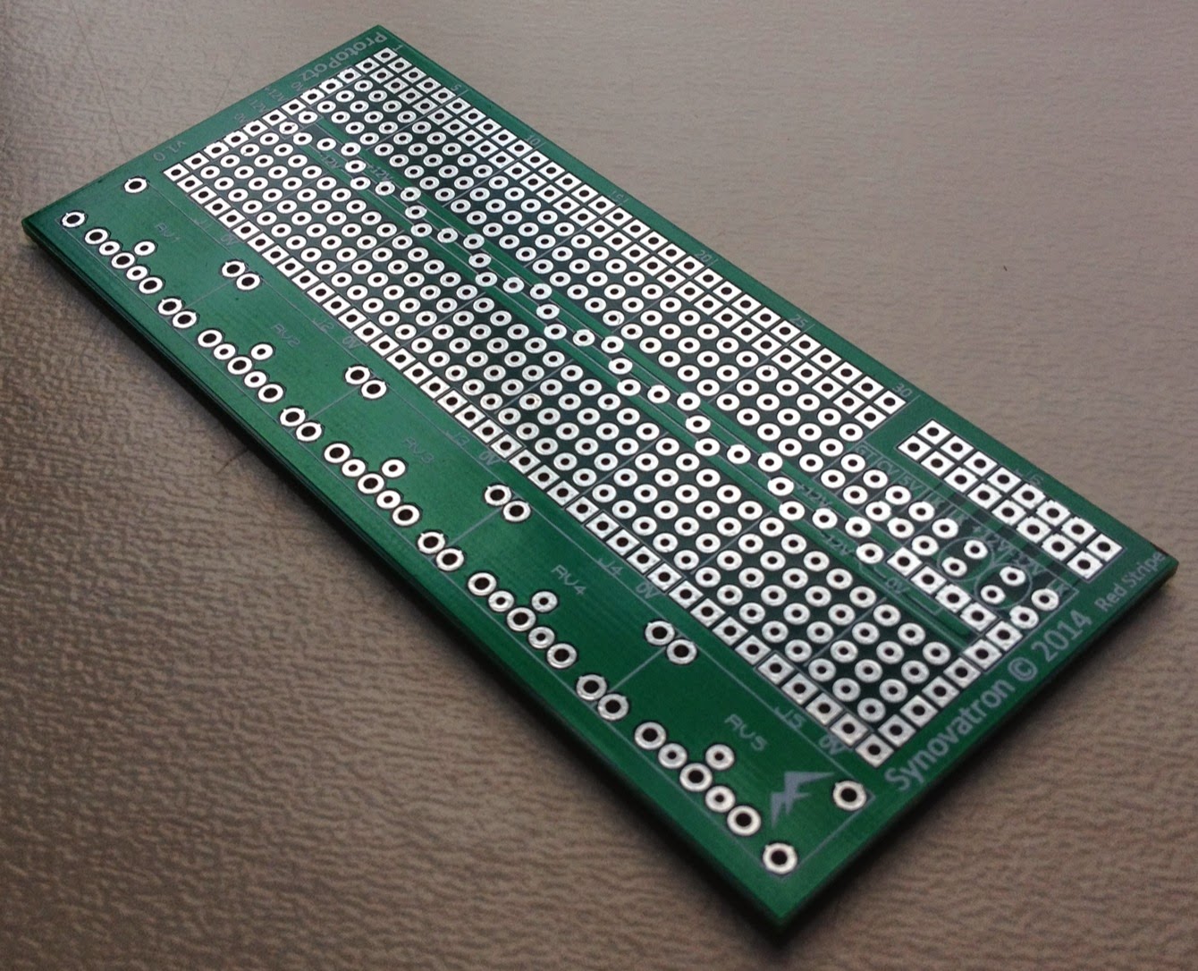
What has emerged is a revised and rebranded Eurorack prototyping solution that is more usable and more elegant than before. The revised product revolves around three PCBs in the Synovatron Proto series: ProtoPotz, ProtoJax and ProtoXp

The new Proto PCBs' holes line up with each other to allow each board to be stacked one on the other using header plugs and sockets; allowing power and signals to be routed between boards without resorting to linking ribbon cables. Here is an example board stack-up:

ProtoJax, ProtoPotz and ProtoXp boards stacked together


Examples of headers and sockets used to stack the boards

ProtoPotz

ProtoPotz is the direct replacement for DIY1 PCB (as used in DIY Kit 1 and DIY Kit 2). It is designed to hold up to five 16mm P160KN series pots using brackets. What's new about it?
  • Plated-through holes for robustness and convenience, essentially it's a double-sided PCB. 
  • Better supports the A-100 bus with dedicated positions for 10 or 16-way open or boxed headers, small electrolytic capacitors and protection diodes (to protect against reverse power connection.


ProtoPotz pot breadboard PCB
Here is the range of pots available from Mouser that Synovatron recommends for use with ProtoPotz:-

ProtoJax

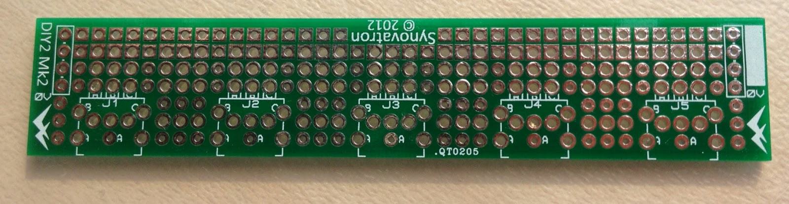
ProtoJax is an evolution of DIY2 and DIY3 PCBs. It is designed to hold up to five Cliff CL1384 3.5mm mono jacks. It is almost identical to ProtoPotz except it has footprints for jacks instead of pots and another two rows of breadboard holes. What makes it more advanced than DIY2 and DIY3 pcbs?
  • Larger breadboarding area. 
  • Supports the A-100 bus similar to ProtoPotz.


ProtoJax jack breadboard PCB

ProtoXp

ProtoXp is a completely new PCB. It is an eXpansion board designed to add more breadboarding area to ProtoPotz or ProtoJax boards. It's features are:-
  • It has a cutout that allows the A-100 bus ribbon cable connector to fit without fouling on the ProtoXp board. 
  • The same ±12V power bus structure as the ProtoPotz or ProtoJax boards.


ProtoXp expansion breadboard PCB


DIY2 jack breadboard PCB


DIY3 jack breadboard PCB

Saturday, 11 January 2014

cvgt MM Buchla Translator ModuleModules

The first cvgt MM modules have started shipping to clients at the top of the pre-order list. If you want to be added to the list then please make contact on synovatron@btinternet.com

I will build in small batches and work through the list in chronological order and will then contact you when your order is ready to ship. Only at that point will I request payment (see prices below). Please note that this does not form any contract between us and you are not in any way commiting yourself to making a purchase until such a time that you make a payment.
 
Initially the cvgt MM will be only available directly from me but if there is enough demand then it is possible they will become available at all the usual distributors in due course. 

The current variants are:-
  • Buchla-Euro (round or hex nuts on 3.5mm jacks; please select)
  • Buchla-Serge*
  • Buchla-BugBrand*
  • Buchla-Fenix*
*These are banana socketed variants and only the colour of the banana sockets is different (to match the target system); All are variants (inc. Euro) are to translate from Buchla to 1V/octave systems.

The User Manual is being worked on and will be ready very soon and will posted here in an update. Please checkout the Eardrill website for more info on the ModuleModule concept and other great products from Chris Muir.


Euro variant
Serge variant
Euro (top), Serge (bottom)


Friday, 6 December 2013

cvgtMM - A ModuleModule version of the CVGT1

This project has kept me busy for the past few months. It was suggested some while ago that I do a ModuleModule version of CVGT1 to go in a Buchla (see my earlier post). My initial thoughts were that it was probably not the best solution as front panel space in a ModuleModule is quite restricted and Buchla real-estate is not cheap. However what I didn't consider was that Buchla can also talk to Serge, BugBrand, Fenix etc and Serge users seemed to want this solution. Consequently I set about designing (or redesigning) CVGT1 to fit in a ModuleModule form factor. Chris Muir from Eardrill produced a great interface document which defines just about all I needed to know for designing a ModuleModule (I'll refer to ModuleModule as MM from now on). 

Because of the smaller front panel space I had to lose some features i.e. scaling and offset on the Buchla to other synth CV channel but as it is in a Buchla and will interface to an external 1V/octave synth I've fixed the scaling at 0.8333 (1/1.2) and zero offset. The PCB design allows either 3.5mm jacks or 4mm bananas to be fitted; so one PCB can be configured to for Euro or Serge etc.


Clearly this design has PCBs parallel to the front panel unlike CVGT1 which has them perpendicular hence the change in jack style.  The PCBs had a completely new layout with all front panel related parts on the first board (Front Panel Interface Board) and most of the circuitry on the second (Main Board). Here are some design images of the variants (there are a few very minor tweeks to the graphic since this was drawn and you'll see a few variations in the prototype pics below).


I built a prototype and that's all working nicely. Aside from the new PCB layouts I had to make some changes to the pulse/trigger/gate circuits to run from ±15V rather than ±12V but there were no major changes. Heres a scope image of the Buchla compatible pulse I achieved:-


Here's the prototype with an ink jet printed plastic overlay on the front panel.


All components are conventional through-hole types - I may go over to surface mount if I get more orders than I can personally cope with but think I will still retain through-hole if anyone fancies a kit. You will also notice that the scaling trimmers are front-panel accessible (with a small screw driver) however these are for very fine trimming ±0.5%.

The first pre-production modules will be available in just over a week when the screen-printed panels are in stock. I have a number of interested 'customers' that I will contact soon and will start a pre-order list; please feel free to contact me to get on the list: It will be a 'no-commitment no money up front' arrangement as before with CVGT1 and I will poll all interested parties in turn when I have a module ready to ship to see if you want one. I have not finalised a price yet but guess it will be in the same ballpark as Eardrill's own range of single panel medium complexity MMs.

It will be interesting to see how this takes off, CVGT1 started slow and now there are 200 out there with bags of interest still.  I will do an update in the next week or so. Thanks for reading.

Tuesday, 1 October 2013

Another custom built Euro to Buchla Translator module

I was recently commissioned by a client to build a custom Euro Buchla interface module, similar to the two I previously built, but with offset switching. The previous two designs both had fixed offset and gain and were intended for use with envelopes, LFOs etc. In other words there was no 1V/octave to 1.2V/octave scaling required just offsetting to ensure the Euro signals stayed in the 0-10V range of the Buchla (you can refer back to my earlier post here).


This module is intended to be used alongside my client's CVGT1 module (which provides the ground reference connection) and adds more CV channels. My client uses Expert Sleepers' SilentWay software for pitch sensitive CV and was not interested in scale conversion as the software does the necessary recalibration however he also wanted the flexibility to be able to interface envelopes, transients and LFOs and so wanted to be able to DC shift signals when he needed to.

The spec was 4 channels of Euro to Buchla (scale of 1, 0V or +5V offset) and 1 channel of Buchla to Euro (scale of 1, 0V or -5V offset); so 10 connectors a 5 switches in 8HP.  

My 8HP prototyping panels proved to be difficult as the existing hole positions meant that the connectors and switches would have been too close to each other plus I only had a few left and found they were scratched; they got binned. I used Schaeffer for a quick-turnaround panel; not cheap but very well made. In a moment of madness I got 5 panels made, including engraving (which the original 2 modules didn't have).


Tuesday, 25 June 2013

Some Preliminary Work on a ModuleModule Design

ModuleModule CV and gate/trigger translator


This is just a quick post to show what I have been doing with regard to the ModuleModule design I mentioned in my last blog post. More info will unfold over the next weeks but this is just to let several Muffwigglers know that I am progressing their ideas (albeit a bit slowly). These are just a first draft and the design will change. The idea is that there will be a common design that supports either Buchla/Euro or Buchla/Serge; the only difference being the connectors used. It's difficult fitting all I want in the smaller ModuleModule format - perhaps the trim pots will come out and I'll add scale switches as per the CVGT1 - your feedback would be valuable!


CV2 - a sister module for the CVGT1


This is another idea I've been mulling over which will complement the CVGT1 and is intended for non-pitch critical CVs and for audio level translation. Again it's just a preliminary idea and feedback is welcomed.


Tuesday, 1 January 2013

Wishing you all a happy 2013

2012 for various reasons has been for me a real struggle and so am hoping 2013 will turn out to be a better year. My wish on this first day of 2013 is that it will be a very happy and healthy year for you and your loved ones.

2012 saw just a few successes:-

The first was the power system and trunk-line modules I designed and built for Gregg Wilson's wonderful wall sized monster synth.


The second was the development, prototyping (including two custom built modules) and preproduction run of the CVGT1 Euro Buchla translator module which are now delivered to the pre-order list customers who are putting them to good use.

Related to the CVGT1 was my first foray into surface-mount boards - the preproduction run of 30 CVGT1 modules used through-hole components which meant that I could, and did, hand build those modules. However they were so time consuming to build that I got quotes for getting them made but the cost was was prohibitive; I was advised that surface mount assembly would be much cheaper and so I set about relaying the boards for surface mounted components.  This worked well and they worked first time albeit for the most significant financial commitment I have made in Synovatron to date. 

CV Tools may get the same reworking but will keep the through-hole version in existance for you DIY enthusiasts; the CV Tools DIY Kit has continued to be a succesful product with more plaudits about the kit presentation, clear instructions and ease of build.

The downside for 2012:-

  
Following a personal loss in July I took some time out and then I pushed very hard in the last 2-3 months to produce a large batch of CV Tools and CVGT1 modules for the end of 2012 but due to supplier quality issues it now looks like those modules will not ship to distributors until late January to early February

I had to reject two thirds of CVGT1 front panels due to scratches and had to reject a batch of 1000 jack sockets due to varying quality from stiff to non-functional (i.e. can't insert a patch lead); unfortunately many were assembled on boards before I discovered this. So all in all a huge amount of effort and frustration with no output but I have learned lessons from this. 3.5mm connector quality is certainly the hardest component problem that Eurorack manufacturers seem to face followed closely by front panel quality issues.

Another problem encountered but Eurorack users is the ease of misconnecting the power cable. 


This was brought sharply into focus by a client who reverse connected his RS-35 using one of my ASM2DB Adaptors and blew up the tantalum capacitors and a CA3046 IC on the RS-35; notably all the TL072 ICs survived as did the F-V converter chip

The connection instructions are clear but we are human and our capacity to f**k up goes with the territory (hence the disclaimer in the instructions); I still do it even though I know to be careful. I have fixed his module for free as a goodwill gesture but it does worry me - my plea to all designers of new modules is use protection diodes.

Saturday, 13 October 2012

Euro and Buchla working together

Here's a short video by Eldancer showing the buchla and Euro systems workng together. Both the CVGT1 and a custom euro Buchla interface module I made a while back are in use here (top right hand corner). They don't get the limelight, they just allow the conversation to occur, working quitely in the background :)


mutipatch 1 from Eldancer on Vimeo.

A quick update on CVGT1 Modules

About half of my pre-order list for CVGT1 modules have been delivered and the rest will go out within the next month. Within a couple of months they will appear with distributers but I am having to look at relaying the boards for surface mount to keep assembly costs down - I don't want the price to go up and I cannot keep building them myself - after building 60 CV Tools and 20 CVGT1 modules (220 circuit boards in all) I am all soldered out. CV Tools will also get relaid for surface mount but I will still keep a through hole stock (currently sold out) for DIY kits.  Watch out for my next update in a month.

Tuesday, 17 July 2012

Announcing Synovatron's second module CVGT1

Sneak preview

The new module is a Eurorack format Eurorack/Buchla translator called CVGT1. It allows Eurorack and Buchla synths to interact with each other, as the name suggest it provides a CV and a Gate/Trigger interface. Not only does it provide the correct format connectors (and adheres to the Buchla color code) but it also deals with the CV scaling and offsetting and the gate/trigger and timing pulse conversion required to allow control in both directions.

The module is in final stages of build and will need to undergo design proving tests before I release it into the world. So far the front panels are complete and all the components are in stock except for the slightly important PCBs which are due in tomorrow (18th July 2012). The intended launch date is Saturday 21st July at the Brighton Modular Meet at the University of Sussex just outside Brighton UK. 

Here are some quick photos of the panels and partial assembly.  I will follow up in a few days with better photos of the fully assembled module, further details and User Manual download link.


Saturday, 12 May 2012

I Dream of Wires 2: A documentary

A very inspirational video; certainly from my perspective as a small manufacturer of synth modules. Modcan's Bruce Duncan and Intellijel's Danjel Van Tijn give the low-down on their synth building ethos. I have huge respect for these guys for their achievements, products and thinking. Check this out. 

Tuesday, 10 April 2012

Euro to Buchla CV Interface Module

I was commissioned by a client to design and build an interface module that allowed his Euro synth to modulate his Buchla synth and vice-versa.

Format Jumbler?

Euro uses 3.5mm mini jack sockets and Buchla uses 4mm banana sockets (which are colour coded). However this design is not just a 'format jumbler' because aside from the connector differences the signal ranges are different.  Buchla uses CV signals in the range of 0V to +10V and Euro uses nominally ±5V (well actually anywhere between -11ish Volts to +11ish Volts).  My client wanted 4 channels of Euro to Buchla and 1 channel of Buchla to Euro. 

Design Spec

The design spec I settled on was ±5V in (Euro) gives 0V to +10V out (Buchla) on channels 1 to 4 and 0V to +10V in (Buchla) gives ±5V out (Euro) on channel 5. As you can see the inputs and outputs both have 10V swings and so a gain of 1 is required but with a 5V offset (-5V one way and +5V the other). The input impedance of 100k and output impedance of 1k was used as it's fairly standard.  I used clamping diodes on the Buchla outputs so that an input more negative than -5V didn't cause a negative output to the Buchla. Because there might not be a common ground reference between the two synths a GND socket was also added to the design. Note that Buchla colour coding uses black for CV outputs and ground connections, blue for CV inputs.

Implementation

As the job was for just one module I used one of my standard 8HP front panels (order code 8HPP) and a new DIY prototyping PCB (order code DIY3) to build the design onto. 

The 8HPP front panel has 10 3mm pilot holes which had to be opened out to fit the 4mm and 3.5mm sockets plus a new hole for the GND socket. I settled on the position for the GND socket equidistant between the four lowest connectors really just for best spacing; I looked at putting it below the lowest two connectors but decided (incorrectly) that there would be not enough space to get fingers in and also avoid the mounting rail.

8HPJ (left) and 8HPP (right) Front Panels


The DIY3 is a bigger version of the DIY2 prototyping board and allows more complex circuitry to be realised due to the larger breadboarding area, power rail support for op-amps and A-100 Bus support (it is effectively a hybrid between DIY1 and DIY2 boards). The idea behind DIY3 was to be able to do more with jack-socket only designs such as buffered mults and attenuators, amplifiers, logic and gate/trigger circuits etc.

DIY3 Prototyping Board

The First Module

Here is the first module which I'm pleased with. It showcases the DIY prototyping board's capability nicely. The client was happy too.


The Second Module

On the back of the first order another client expressed an interest in the same functionality but preferred the GND socket to go below the lower two connectors. There was enough room to clear the mounting rail but pushes it closer to the channel 5 connectors than is ideal but still looks ok.


Further Modules?

I have another two expressions of interest for these modules especially if they were production rather than prototype versions. One suggestion was for front panel graphics to be added using the same font/style as Buchla which I like the idea of. Another thought is that not just CV translation is useful, gate/trigger translation would be useful too (as they are not compatible between the two 'standards'). I could also provide these as very basic kits (all the bits you need, a circuit diagram and a layout pattern). If I can get a few more interested parties to make it viable I would consider a small production run with purpose designed PCBs and a screen printed front panel. So if there is any interest out there please make your thoughts known to me.


Saturday, 28 January 2012

Trunk-line Module

I was commissioned by a client to make some Trunk-line Modules. These are similar to the Analogue Systems RS-250 module but offer rear facing jack sockets instead of unterminated jacks that you have to solder wires to and is ideal if soldering is not your thing.

8HP 10-channel Trunk-line Module front jacks

8HP 10-channel Trunk-line Module rear jacks
The point of a Trunk-line module is to provide front panel access to either outboard equipment such as mixers, sound cards, MIDI/CV units etc., or to provide connection across a very large synth (using two modules) so you don't have to use very long patch cables on the front panel. Most of us don't have big enough synths to warrant this so these really are for large synths that are more like installations.

The photos show an 8HP 10-channel module; I have made a few of these modules to order and because of the small quantities involved there are no screen-printed markings (due to the setup costs). I'd like to know if anyone else would be interested in a Trunk-line module and, if there were large enough numbers, I'd do a small production run with screen printed markings, so please let me know; I could also do a 4HP 5-channel version and versions with solderable sockets too.

Tuesday, 22 November 2011

Modular in a tool case

I had a day free on Saturday and set about putting a modular in a tool case. To be exact it is a Doepfer A-100 DIY kit #1 fitted to a Halfords engineers tool case. The point of this was to have an easily transportable demo system so I can take to shows, meets etc in order to show how lovely my CV Tools module is and to let people have a play.

In a follow-on to my cheap DIY store front panels post a few weeks back I used anodised aluminium angle strips in the construction from Homebase - the case is bigger than the 6U 84HP of the rack kit.
(Note to non-UK readers Halfords is a motor accessories store and Homebase is a DIY store)

Here's the case


Prep the case - remove separators, tool panel and unecessary fixings.

All done, ready to start serious modding

This will be powered by a 15VAC supply so a nice big hole for an XLR connector

XLR in place (EDIT: this is eventually replaced by a plug version as a power lead with exposed pins is bad karma)

A bit of judiscious foam cutting to neaten it up

Markout and drill the regulator boards fixing points - 4 x M3

Regulator screwed in place

I used M3 washers to spread the load - the case is just hardboard with a thin aluminium veneer

Position the bus boards and drill mounting holes - long M3 screws with tapped spacers fitted

All electrics now in place. Note this is temporary - there will be wiring to a front panel power switch on the next installment!

Next make the rack end pieces out of 10mm x 20mm anodised aluminium angle strip. These make the rack the perfect width to fit the case.

Similar to above I made top and bottom strips to fill the gap - I used 25mm x 25mm anodised angle, again an almost exact height fit - starting to look good.

Here's a view showing the fixings (ok I drilled a hole in the wrong place. Motto: measure twice, cut once!!!).

As I said a near perfect fit in the case. At this point just resting on the foam and not screwed in. That's in the next installment.

Loaded with modules and powered up. Take no notice of the modules selection, I've since changed it to a more coherent set.

Even a nifty scope showing VCOs, Synovatron DioDe and CV Tools in operation - now that's a waveform!

 Next installment will add a power switch and fixings to anchor the rack to the case. It will also make use of all that front panel space top and bottom for passive and buffered mults, bus access, simple LFOs, gate logic, 3.5mm to 6.25mm/RCA adaptors, etc etc (the thought of the lovely goodies that will get built in is going to keep me awake a night - so sad!!)

Here's a short clip of it working:-