Showing posts with label 8HP. Show all posts

Saturday, 12 July 2014

Eurorack DIY Prototyping Cards Rethink

Post updated 3rd July 2018

The Synovatron Eurorack DIY Kits have now been discontinued. Because many of the kit components are easily available from online retailers it made sense that Synovatron just provides the unique (e.g. PCBs) and harder to source parts (e.g. pot brackets). This provided a great opportunity to reassess the PCB designs rather than just reorder more of the same.

What has emerged is a revised and rebranded Eurorack prototyping solution that is more usable and more elegant than before. The revised product revolves around three PCBs in the Synovatron Proto series: ProtoPotz, ProtoJax and ProtoXp

The new Proto PCBs' holes line up with each other to allow each board to be stacked one on the other using header plugs and sockets; allowing power and signals to be routed between boards without resorting to linking ribbon cables. Here is an example board stack-up:

ProtoJax, ProtoPotz and ProtoXp boards stacked together


Examples of headers and sockets used to stack the boards

ProtoPotz

ProtoPotz is the direct replacement for DIY1 PCB (as used in DIY Kit 1 and DIY Kit 2). It is designed to hold up to five 16mm P160KN series pots using brackets. What's new about it?
  • Plated-through holes for robustness and convenience, essentially it's a double-sided PCB. 
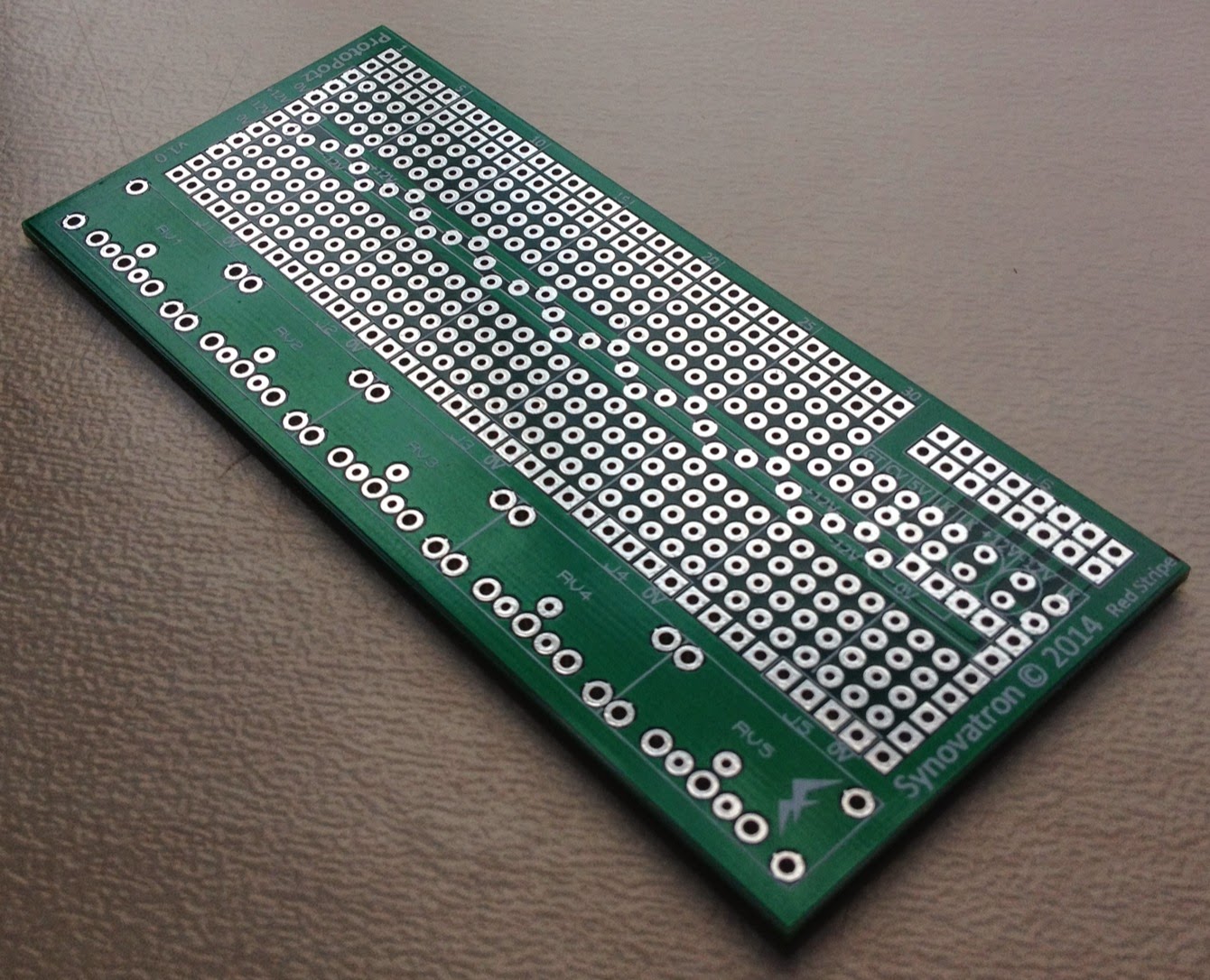
  • Better supports the A-100 bus with dedicated positions for 10 or 16-way open or boxed headers, small electrolytic capacitors and protection diodes (to protect against reverse power connection.


ProtoPotz pot breadboard PCB
Here is the range of pots available from Mouser that Synovatron recommends for use with ProtoPotz:-

ProtoJax

ProtoJax is an evolution of DIY2 and DIY3 PCBs. It is designed to hold up to five Cliff CL1384 3.5mm mono jacks. It is almost identical to ProtoPotz except it has footprints for jacks instead of pots and another two rows of breadboard holes. What makes it more advanced than DIY2 and DIY3 pcbs?
  • Larger breadboarding area. 
  • Supports the A-100 bus similar to ProtoPotz.


ProtoJax jack breadboard PCB

ProtoXp

ProtoXp is a completely new PCB. It is an eXpansion board designed to add more breadboarding area to ProtoPotz or ProtoJax boards. It's features are:-
  • It has a cutout that allows the A-100 bus ribbon cable connector to fit without fouling on the ProtoXp board. 
  • The same ±12V power bus structure as the ProtoPotz or ProtoJax boards.


ProtoXp expansion breadboard PCB


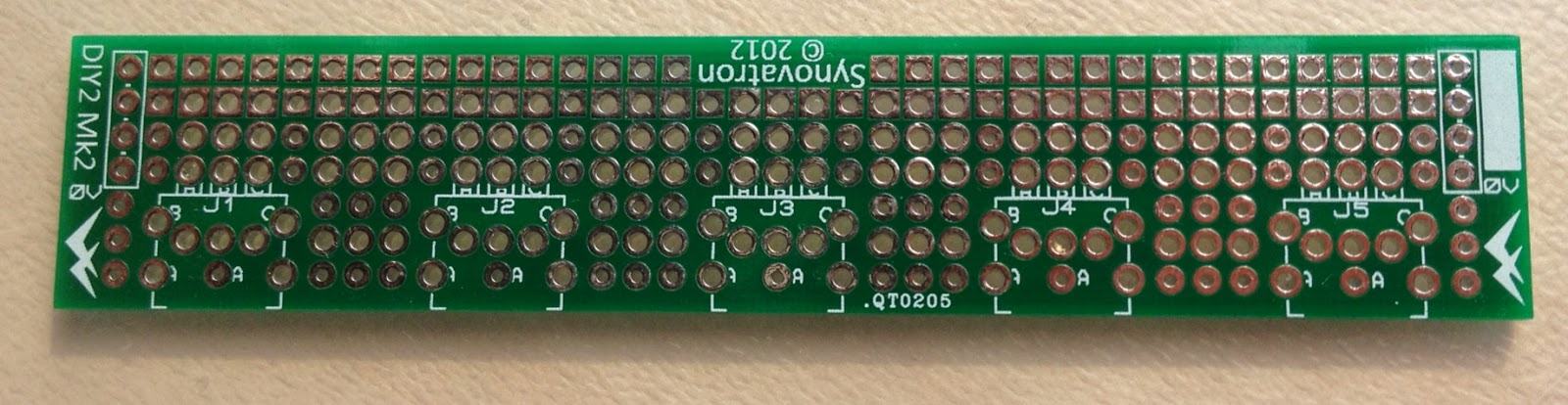
DIY2 jack breadboard PCB


DIY3 jack breadboard PCB

Tuesday, 1 October 2013

Another custom built Euro to Buchla Translator module

I was recently commissioned by a client to build a custom Euro Buchla interface module, similar to the two I previously built, but with offset switching. The previous two designs both had fixed offset and gain and were intended for use with envelopes, LFOs etc. In other words there was no 1V/octave to 1.2V/octave scaling required just offsetting to ensure the Euro signals stayed in the 0-10V range of the Buchla (you can refer back to my earlier post here).


This module is intended to be used alongside my client's CVGT1 module (which provides the ground reference connection) and adds more CV channels. My client uses Expert Sleepers' SilentWay software for pitch sensitive CV and was not interested in scale conversion as the software does the necessary recalibration however he also wanted the flexibility to be able to interface envelopes, transients and LFOs and so wanted to be able to DC shift signals when he needed to.

The spec was 4 channels of Euro to Buchla (scale of 1, 0V or +5V offset) and 1 channel of Buchla to Euro (scale of 1, 0V or -5V offset); so 10 connectors a 5 switches in 8HP.  

My 8HP prototyping panels proved to be difficult as the existing hole positions meant that the connectors and switches would have been too close to each other plus I only had a few left and found they were scratched; they got binned. I used Schaeffer for a quick-turnaround panel; not cheap but very well made. In a moment of madness I got 5 panels made, including engraving (which the original 2 modules didn't have).


Tuesday, 25 June 2013

Some Preliminary Work on a ModuleModule Design

ModuleModule CV and gate/trigger translator


This is just a quick post to show what I have been doing with regard to the ModuleModule design I mentioned in my last blog post. More info will unfold over the next weeks but this is just to let several Muffwigglers know that I am progressing their ideas (albeit a bit slowly). These are just a first draft and the design will change. The idea is that there will be a common design that supports either Buchla/Euro or Buchla/Serge; the only difference being the connectors used. It's difficult fitting all I want in the smaller ModuleModule format - perhaps the trim pots will come out and I'll add scale switches as per the CVGT1 - your feedback would be valuable!


CV2 - a sister module for the CVGT1


This is another idea I've been mulling over which will complement the CVGT1 and is intended for non-pitch critical CVs and for audio level translation. Again it's just a preliminary idea and feedback is welcomed.


Tuesday, 17 July 2012

Announcing Synovatron's second module CVGT1

Sneak preview

The new module is a Eurorack format Eurorack/Buchla translator called CVGT1. It allows Eurorack and Buchla synths to interact with each other, as the name suggest it provides a CV and a Gate/Trigger interface. Not only does it provide the correct format connectors (and adheres to the Buchla color code) but it also deals with the CV scaling and offsetting and the gate/trigger and timing pulse conversion required to allow control in both directions.

The module is in final stages of build and will need to undergo design proving tests before I release it into the world. So far the front panels are complete and all the components are in stock except for the slightly important PCBs which are due in tomorrow (18th July 2012). The intended launch date is Saturday 21st July at the Brighton Modular Meet at the University of Sussex just outside Brighton UK. 

Here are some quick photos of the panels and partial assembly.  I will follow up in a few days with better photos of the fully assembled module, further details and User Manual download link.


Tuesday, 10 April 2012

Euro to Buchla CV Interface Module

I was commissioned by a client to design and build an interface module that allowed his Euro synth to modulate his Buchla synth and vice-versa.

Format Jumbler?

Euro uses 3.5mm mini jack sockets and Buchla uses 4mm banana sockets (which are colour coded). However this design is not just a 'format jumbler' because aside from the connector differences the signal ranges are different.  Buchla uses CV signals in the range of 0V to +10V and Euro uses nominally ±5V (well actually anywhere between -11ish Volts to +11ish Volts).  My client wanted 4 channels of Euro to Buchla and 1 channel of Buchla to Euro. 

Design Spec

The design spec I settled on was ±5V in (Euro) gives 0V to +10V out (Buchla) on channels 1 to 4 and 0V to +10V in (Buchla) gives ±5V out (Euro) on channel 5. As you can see the inputs and outputs both have 10V swings and so a gain of 1 is required but with a 5V offset (-5V one way and +5V the other). The input impedance of 100k and output impedance of 1k was used as it's fairly standard.  I used clamping diodes on the Buchla outputs so that an input more negative than -5V didn't cause a negative output to the Buchla. Because there might not be a common ground reference between the two synths a GND socket was also added to the design. Note that Buchla colour coding uses black for CV outputs and ground connections, blue for CV inputs.

Implementation

As the job was for just one module I used one of my standard 8HP front panels (order code 8HPP) and a new DIY prototyping PCB (order code DIY3) to build the design onto. 

The 8HPP front panel has 10 3mm pilot holes which had to be opened out to fit the 4mm and 3.5mm sockets plus a new hole for the GND socket. I settled on the position for the GND socket equidistant between the four lowest connectors really just for best spacing; I looked at putting it below the lowest two connectors but decided (incorrectly) that there would be not enough space to get fingers in and also avoid the mounting rail.

8HPJ (left) and 8HPP (right) Front Panels


The DIY3 is a bigger version of the DIY2 prototyping board and allows more complex circuitry to be realised due to the larger breadboarding area, power rail support for op-amps and A-100 Bus support (it is effectively a hybrid between DIY1 and DIY2 boards). The idea behind DIY3 was to be able to do more with jack-socket only designs such as buffered mults and attenuators, amplifiers, logic and gate/trigger circuits etc.

DIY3 Prototyping Board

The First Module

Here is the first module which I'm pleased with. It showcases the DIY prototyping board's capability nicely. The client was happy too.


The Second Module

On the back of the first order another client expressed an interest in the same functionality but preferred the GND socket to go below the lower two connectors. There was enough room to clear the mounting rail but pushes it closer to the channel 5 connectors than is ideal but still looks ok.


Further Modules?

I have another two expressions of interest for these modules especially if they were production rather than prototype versions. One suggestion was for front panel graphics to be added using the same font/style as Buchla which I like the idea of. Another thought is that not just CV translation is useful, gate/trigger translation would be useful too (as they are not compatible between the two 'standards'). I could also provide these as very basic kits (all the bits you need, a circuit diagram and a layout pattern). If I can get a few more interested parties to make it viable I would consider a small production run with purpose designed PCBs and a screen printed front panel. So if there is any interest out there please make your thoughts known to me.


Saturday, 28 January 2012

Trunk-line Module

I was commissioned by a client to make some Trunk-line Modules. These are similar to the Analogue Systems RS-250 module but offer rear facing jack sockets instead of unterminated jacks that you have to solder wires to and is ideal if soldering is not your thing.

8HP 10-channel Trunk-line Module front jacks

8HP 10-channel Trunk-line Module rear jacks
The point of a Trunk-line module is to provide front panel access to either outboard equipment such as mixers, sound cards, MIDI/CV units etc., or to provide connection across a very large synth (using two modules) so you don't have to use very long patch cables on the front panel. Most of us don't have big enough synths to warrant this so these really are for large synths that are more like installations.

The photos show an 8HP 10-channel module; I have made a few of these modules to order and because of the small quantities involved there are no screen-printed markings (due to the setup costs). I'd like to know if anyone else would be interested in a Trunk-line module and, if there were large enough numbers, I'd do a small production run with screen printed markings, so please let me know; I could also do a 4HP 5-channel version and versions with solderable sockets too.

Wednesday, 2 March 2011

New generic front panels for DIY kits

I now have stock of a range of 4HP and 8HP front panels to suit the Synovatron DIY Prototyping Kits. These can be purchased with the kits as an option or separately. 


The 8HP panel suits DIY Kit 1 and has two variants, one to suit a column of jacks (8.2mm holes) and a column of pots (7.5mm holes). The other variant has 3mm pilot holes to give you the flexibility to mix and match front panel components by drilling out to suit jacks, pots or switches, or left as is for 3mm LEDs.

The 4HP panel suits DIY Kit 3 and also has two variants, one to suit jack sockets (8.2mm holes) and the other with just 3mm pilot holes so they can easily be modified to larger diameters for jacks or switches or left as is for LEDs.

The panels are made from 2mm aluminium and have a brushed, clear anodised finish.  The mounting holes (slots) are suitable for both Doepfer and Analogue Systems hole pitches.

These panels make the kits more complete and I will also offer a set of knobs in DIY Kit 1 to finish it off.

Kit 1 options: The soft-touch knobs can be ordered in white, grey, red, orange, yellow, green or blue.
Prices range from £5.99 to £8.99 if ordered separately, a bit cheaper if ordered with a kit. The knobs are £1.25 for 5 if ordered with a kit.

The panels will also include a set of M3x6 screws and plain washers.

Update:
Here's a 8HP pilot hole panel that I drilled out for a customer so he could mount a mult on the left and an OSC303 on the right (Note: he bought the OSC303 as a kit without front panel and jacks. There's no point in trying to do this if you have one DinSyncs's excellent clear blue panels). The jacks were drilled out to 8mm, the pot to 7.5mm and the switch to 6mm. Looks pretty sexy!

Tone's top tips:  
(1) Cover the panel in masking tape so the swarf doesn't scratch the front finish. 
(2) start with smaller drill sizes and work up to the final size else you may end up with odd shaped holes.
(3) Deburr holes on both sides with a countersink bit.