Saturday, 27 September 2014

Synth Repairs


Analogue Systems RS-40 Noise, Sample and Hold, Osc


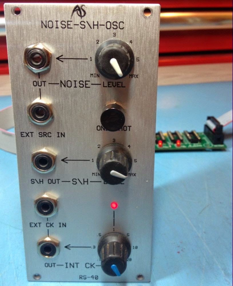
This came in as 'defective'. After a while it became obvious the noise output was not working. This was traced to an open-circuit LEVEL contol pot (10k lin) which was replaced. Still it didn't work as a sample and hold - i.e. I was expecting to see a stepped output from S\H OUT. Not having used the RS-40 before it took me a while to realise that the noise and clock signals are not normalled to the Sample and Hold circuit like the front panel markings suggest; the lines linking NOISE OUT to EXT SRC IN and INT CK OUT to EXT CK IN suggest to me these are linked in some way but no. 
RS-40
After looking at the jacks it was clear that these are not normalled (I'm not sure if this is the case with all RS-40s but this one looked clean and unmodified so I'm assuming it was factory standard). I used external patch leads and to link the noise and clock outs and ins and hey presto it worked. The first thing that I saw on the scope was at each sample point the sampled signal is present for what I guess is the duration of the sample pulse (about 0.2ms). When using the RS-40 to modulate a VCO I could not tell that the noise spikes were a problem, in fact it is probably above hearing range (at least mine). 
 
Noise spikes

However I didn't much like it and I didn't much like not having the noise and clock not normalled to the S/H circuit. I spoke to the owner and he agreed to have a couple of simple mods applied.

The noise and clock signals are present on the jack board close to where they would have to go for normalled connections. The switched contacts were connected to ground on both EXT SRC IN and EXT CK IN jacks by solder bridges. I removed the solder bridges and fitted links as can be seen here. This worked a treat allowing it to work without patching but still allowing external signals to be patched in if need be.

Solder removed from red arrows and links applied at yellow arrows
The noise spikes 'problem' although not audible was fixed by placing a 10nF cap across the S/H output amplifier's feedback resistor (27k) making it a low-pass filter with a cutoff of 590Hz. This got rid of the spikes without adding noticeable slew.

10nF capacitor

Spike free steps


Saturday, 13 September 2014

5 into 1 Analogue Systems to Doepfer Bus Adaptor/Expander

The new 5ASM2DB Analogue Systems Module to Doepfer A-100 Bus Adaptor/Expander is now in stock and available to order. 

SchneidersLaden have stock of 5ASM2DB which can be ordered from their website at http://www.schneidersladen.de/en/manufacturer/synovatron.html.

For DIY enthusiasts it is also available as a kit or as a bare PCB direct from Synovatron (please email synovatron@btinternet.com). 

The 5ASM2DB offers five Analogue Systems sockets on one small circuit board with low-current LED indicators to show that ±12V and +5V power is available. It comes with a ribbon cable to connect to the A-100 bus and four self-adhesive nylon PCB mounting pillars (you can of course use screwed in pillars so a drilling template will be provided).

If you have several Analogue Systems modules in a Euro rack then the 5ASM2DB could be a better alternative to using several ASM2DB Adaptors because it expands the bus and frees up A-100 Bus connectors for Euro modules; it costs roughly the same as three ASM2DB Adaptors. ASM2DB and DM2ASB Adaptors are still available.

5ASM2DB Adaptor/Expander
5ASM2DB DIY Kit

Friday, 29 August 2014

New product preview

This is a design that has been hanging around for over a year in a 95% complete state but I have now taken the bold step of finishing it and going into production. It is called the 5ASM2DB and is a 5 socket version of the popular ASM2DB Analogue Systems module to Doepfer bus Adaptor. It is fabricated on a small circuit board and has 3 LEDs that indicate the presence of ±12V and +5V. The 5ASM2DB will be supplied with 4 self-adhesive nylon mounting pillars and a short ribbon cable so it can be placed adjacent to a busboard and linked via the ribbon cable (standard Euro rack 16 pin cable). It is not recommended for use with the Analogue Systems RS-370 as this draws a whoppng 680mA from the 5V rail.

It will be priced at roughly that of 3 ASM2DB Adaptors so the aim is you get 5 for the price of 3; which will be of interest to those of you with many Analogue Systems modules to go in a Eurorack case.

Availability is from mid-September and will also be available as a DIY kit and as a bare PCB for the more adventurous DIYers. Here's an image from the CAD package - it will not be red BTW!


Confused by Cwejman ribbon cables?

I received an order to build some Cwejman standard ribbon cables that were 40cm long. Up until then I had no idea they were different to standard Eurorack cables. So here is what I found out and hopefully this takes the mystery out of it for anyone who is lucky enough to own one of these top modules (and it's also a sales plug - no pun intended).


Saturday, 12 July 2014

Eurorack DIY Prototyping Cards Rethink

Post updated 3rd July 2018

The Synovatron Eurorack DIY Kits have now been discontinued. Because many of the kit components are easily available from online retailers it made sense that Synovatron just provides the unique (e.g. PCBs) and harder to source parts (e.g. pot brackets). This provided a great opportunity to reassess the PCB designs rather than just reorder more of the same.

What has emerged is a revised and rebranded Eurorack prototyping solution that is more usable and more elegant than before. The revised product revolves around three PCBs in the Synovatron Proto series: ProtoPotz, ProtoJax and ProtoXp

The new Proto PCBs' holes line up with each other to allow each board to be stacked one on the other using header plugs and sockets; allowing power and signals to be routed between boards without resorting to linking ribbon cables. Here is an example board stack-up:

ProtoJax, ProtoPotz and ProtoXp boards stacked together


Examples of headers and sockets used to stack the boards

ProtoPotz

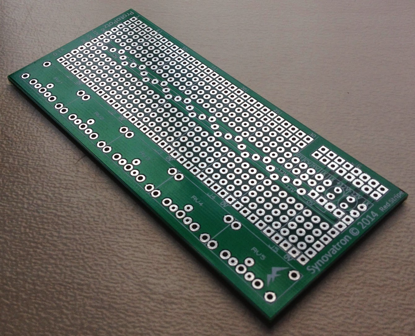
ProtoPotz is the direct replacement for DIY1 PCB (as used in DIY Kit 1 and DIY Kit 2). It is designed to hold up to five 16mm P160KN series pots using brackets. What's new about it?
  • Plated-through holes for robustness and convenience, essentially it's a double-sided PCB. 
  • Better supports the A-100 bus with dedicated positions for 10 or 16-way open or boxed headers, small electrolytic capacitors and protection diodes (to protect against reverse power connection.


ProtoPotz pot breadboard PCB
Here is the range of pots available from Mouser that Synovatron recommends for use with ProtoPotz:-

ProtoJax

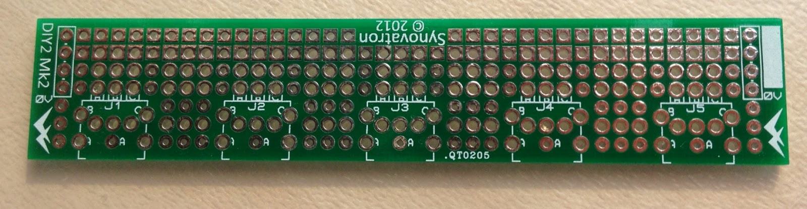
ProtoJax is an evolution of DIY2 and DIY3 PCBs. It is designed to hold up to five Cliff CL1384 3.5mm mono jacks. It is almost identical to ProtoPotz except it has footprints for jacks instead of pots and another two rows of breadboard holes. What makes it more advanced than DIY2 and DIY3 pcbs?
  • Larger breadboarding area. 
  • Supports the A-100 bus similar to ProtoPotz.


ProtoJax jack breadboard PCB

ProtoXp

ProtoXp is a completely new PCB. It is an eXpansion board designed to add more breadboarding area to ProtoPotz or ProtoJax boards. It's features are:-
  • It has a cutout that allows the A-100 bus ribbon cable connector to fit without fouling on the ProtoXp board. 
  • The same ±12V power bus structure as the ProtoPotz or ProtoJax boards.


ProtoXp expansion breadboard PCB


DIY2 jack breadboard PCB


DIY3 jack breadboard PCB

Saturday, 11 January 2014

cvgt MM Buchla Translator ModuleModules

The first cvgt MM modules have started shipping to clients at the top of the pre-order list. If you want to be added to the list then please make contact on synovatron@btinternet.com

I will build in small batches and work through the list in chronological order and will then contact you when your order is ready to ship. Only at that point will I request payment (see prices below). Please note that this does not form any contract between us and you are not in any way commiting yourself to making a purchase until such a time that you make a payment.
 
Initially the cvgt MM will be only available directly from me but if there is enough demand then it is possible they will become available at all the usual distributors in due course. 

The current variants are:-
  • Buchla-Euro (round or hex nuts on 3.5mm jacks; please select)
  • Buchla-Serge*
  • Buchla-BugBrand*
  • Buchla-Fenix*
*These are banana socketed variants and only the colour of the banana sockets is different (to match the target system); All are variants (inc. Euro) are to translate from Buchla to 1V/octave systems.

The User Manual is being worked on and will be ready very soon and will posted here in an update. Please checkout the Eardrill website for more info on the ModuleModule concept and other great products from Chris Muir.


Euro variant
Serge variant
Euro (top), Serge (bottom)


Friday, 6 December 2013

cvgtMM - A ModuleModule version of the CVGT1

This project has kept me busy for the past few months. It was suggested some while ago that I do a ModuleModule version of CVGT1 to go in a Buchla (see my earlier post). My initial thoughts were that it was probably not the best solution as front panel space in a ModuleModule is quite restricted and Buchla real-estate is not cheap. However what I didn't consider was that Buchla can also talk to Serge, BugBrand, Fenix etc and Serge users seemed to want this solution. Consequently I set about designing (or redesigning) CVGT1 to fit in a ModuleModule form factor. Chris Muir from Eardrill produced a great interface document which defines just about all I needed to know for designing a ModuleModule (I'll refer to ModuleModule as MM from now on). 

Because of the smaller front panel space I had to lose some features i.e. scaling and offset on the Buchla to other synth CV channel but as it is in a Buchla and will interface to an external 1V/octave synth I've fixed the scaling at 0.8333 (1/1.2) and zero offset. The PCB design allows either 3.5mm jacks or 4mm bananas to be fitted; so one PCB can be configured to for Euro or Serge etc.


Clearly this design has PCBs parallel to the front panel unlike CVGT1 which has them perpendicular hence the change in jack style.  The PCBs had a completely new layout with all front panel related parts on the first board (Front Panel Interface Board) and most of the circuitry on the second (Main Board). Here are some design images of the variants (there are a few very minor tweeks to the graphic since this was drawn and you'll see a few variations in the prototype pics below).


I built a prototype and that's all working nicely. Aside from the new PCB layouts I had to make some changes to the pulse/trigger/gate circuits to run from ±15V rather than ±12V but there were no major changes. Heres a scope image of the Buchla compatible pulse I achieved:-


Here's the prototype with an ink jet printed plastic overlay on the front panel.


All components are conventional through-hole types - I may go over to surface mount if I get more orders than I can personally cope with but think I will still retain through-hole if anyone fancies a kit. You will also notice that the scaling trimmers are front-panel accessible (with a small screw driver) however these are for very fine trimming ±0.5%.

The first pre-production modules will be available in just over a week when the screen-printed panels are in stock. I have a number of interested 'customers' that I will contact soon and will start a pre-order list; please feel free to contact me to get on the list: It will be a 'no-commitment no money up front' arrangement as before with CVGT1 and I will poll all interested parties in turn when I have a module ready to ship to see if you want one. I have not finalised a price yet but guess it will be in the same ballpark as Eardrill's own range of single panel medium complexity MMs.

It will be interesting to see how this takes off, CVGT1 started slow and now there are 200 out there with bags of interest still.  I will do an update in the next week or so. Thanks for reading.