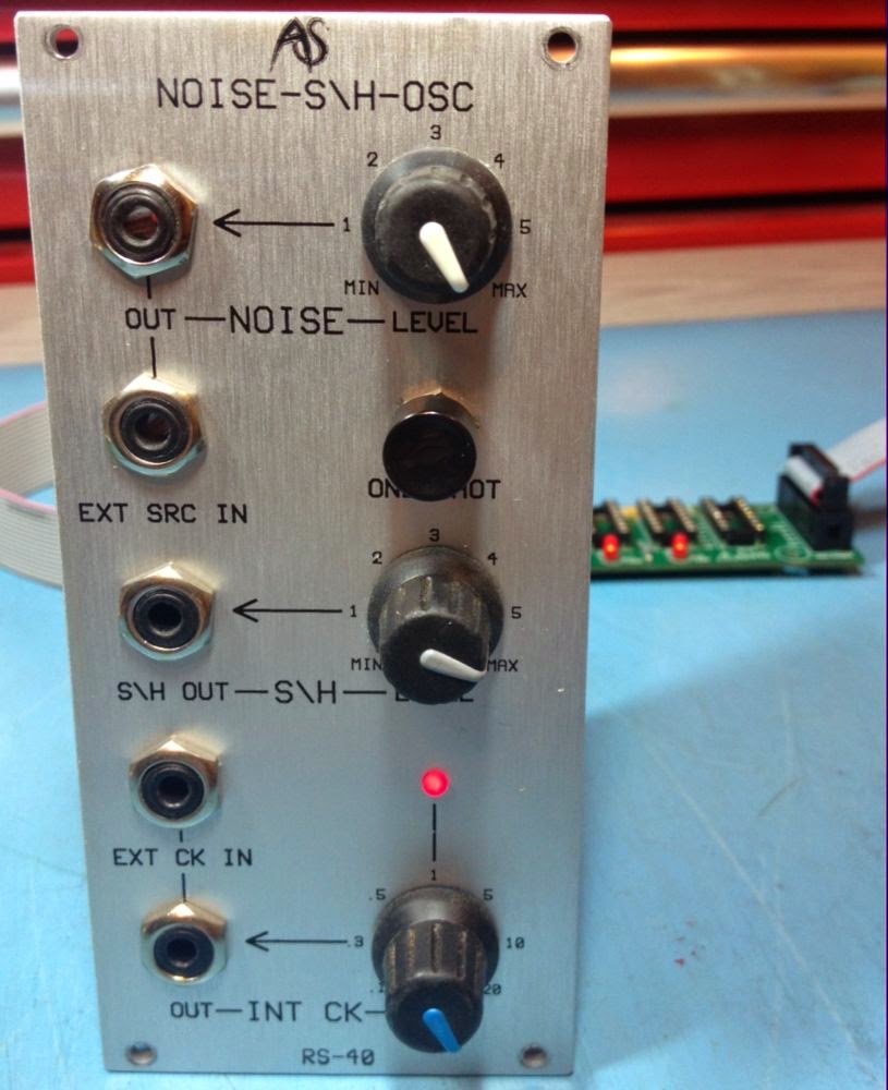
Analogue Systems RS-40 Noise, Sample and Hold, Osc
This came in as 'defective'. After a while it became obvious the noise output was not working. This was traced to an open-circuit LEVEL contol pot (10k lin) which was replaced. Still it didn't work as a sample and hold - i.e. I was expecting to see a stepped output from S\H OUT. Not having used the RS-40 before it took me a while to realise that the noise and clock signals are not normalled to the Sample and Hold circuit like the front panel markings suggest; the lines linking NOISE OUT to EXT SRC IN and INT CK OUT to EXT CK IN suggest to me these are linked in some way but no.
 |
| RS-40 |
 |
| Noise spikes |
However I didn't much like it and I didn't much like not having the noise and clock not normalled to the S/H circuit. I spoke to the owner and he agreed to have a couple of simple mods applied.
The noise and clock signals are present on the jack board close to where they would have to go for normalled connections. The switched contacts were connected to ground on both EXT SRC IN and EXT CK IN jacks by solder bridges. I removed the solder bridges and fitted links as can be seen here. This worked a treat allowing it to work without patching but still allowing external signals to be patched in if need be.
 |
| Solder removed from red arrows and links applied at yellow arrows |
 |
| 10nF capacitor |
 |
| Spike free steps |
No comments:
Post a Comment