EDIT 31May 2015:
For those who have tried to download from links printed on kits, fliers and data sheets etc without success: I apologise but the original file hosting site has shut down without warning in recent weeks. All Synovatron docs have now been rehosted onto Google Docs where they can be viewed or downloaded. The new links are shown on the Support tab above where all downloadable documents will be maintained from now on - if you experience any problems with file downloads please email me at synovatron@btinternet.com. Keep an eye out for new and updated documents. Any additions or significant updates will be announced on the blog as they occur.
The documents added to Google Docs are:-
CV Tools User Manual
CVGT1 User Manual
cvgtMM User Manual
GTPulse Data Pack
ASM2DB Adaptor Fitting Instructions & uZeus Tech Note
DM2ASB Adaptor Fitting Instructions
5ASM2DB Adaptor/Expander Bare Board Data Sheet and Fitting Instructions
Showing posts with label Analogue Systems. Show all posts
Showing posts with label Analogue Systems. Show all posts
Friday, 22 May 2015
Saturday, 17 January 2015
ASM2DB Tech Note for use with uZeus ribbon cable bus
Here is a guide if you are using the uZeus ribbon cable backplane.
 (apologies I didn't have a real uZeus backplane to hand but hopefully you get the idea)
Saturday, 27 September 2014
Synth Repairs
Analogue Systems RS-40 Noise, Sample and Hold, Osc
This came in as 'defective'. After a while it became obvious the noise output was not working. This was traced to an open-circuit LEVEL contol pot (10k lin) which was replaced. Still it didn't work as a sample and hold - i.e. I was expecting to see a stepped output from S\H OUT. Not having used the RS-40 before it took me a while to realise that the noise and clock signals are not normalled to the Sample and Hold circuit like the front panel markings suggest; the lines linking NOISE OUT to EXT SRC IN and INT CK OUT to EXT CK IN suggest to me these are linked in some way but no.
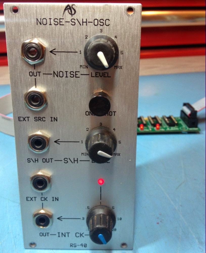 |
| RS-40 |
 |
| Noise spikes |
However I didn't much like it and I didn't much like not having the noise and clock not normalled to the S/H circuit. I spoke to the owner and he agreed to have a couple of simple mods applied.
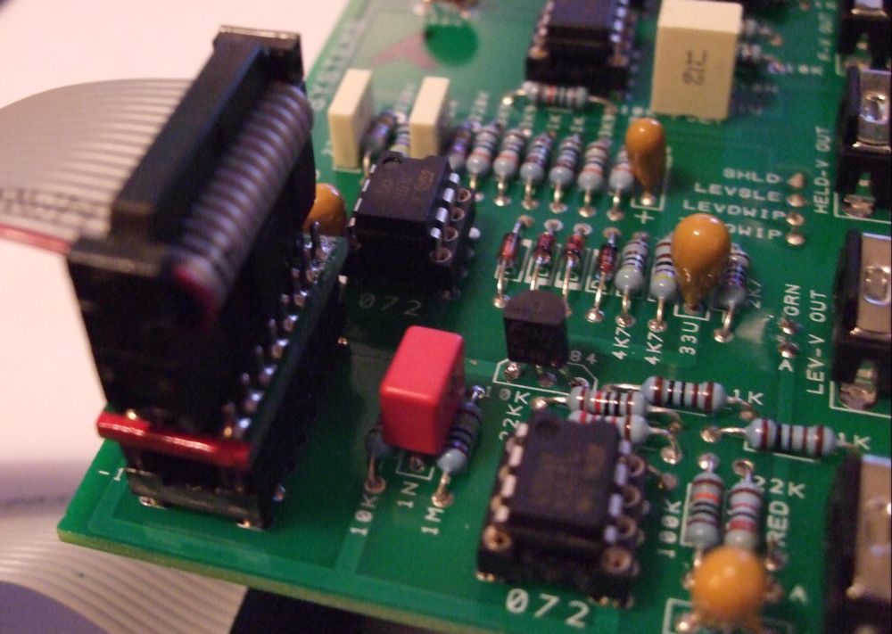
The noise and clock signals are present on the jack board close to where they would have to go for normalled connections. The switched contacts were connected to ground on both EXT SRC IN and EXT CK IN jacks by solder bridges. I removed the solder bridges and fitted links as can be seen here. This worked a treat allowing it to work without patching but still allowing external signals to be patched in if need be.
 |
| Solder removed from red arrows and links applied at yellow arrows |
 |
| 10nF capacitor |
 |
| Spike free steps |
Saturday, 13 September 2014
5 into 1 Analogue Systems to Doepfer Bus Adaptor/Expander
The new 5ASM2DB Analogue Systems Module to Doepfer A-100 Bus Adaptor/Expander is now in stock and available to order.
SchneidersLaden have stock of 5ASM2DB which can be ordered from their website at http://www.schneidersladen.de/en/manufacturer/synovatron.html.
For DIY enthusiasts it is also available as a kit or as a bare PCB direct from Synovatron (please email synovatron@btinternet.com).
The 5ASM2DB offers five Analogue Systems sockets on one small circuit board with low-current LED indicators to show that ±12V and +5V power is available. It comes with a ribbon cable to connect to the A-100 bus and four self-adhesive nylon PCB mounting pillars (you can of course use screwed in pillars so a drilling template will be provided).
If you have several Analogue Systems modules in a Euro rack then the 5ASM2DB could be a better alternative to using several ASM2DB Adaptors because it expands the bus and frees up A-100 Bus connectors for Euro modules; it costs roughly the same as three ASM2DB Adaptors. ASM2DB and DM2ASB Adaptors are still available.
 |
| 5ASM2DB Adaptor/Expander |
 |
| 5ASM2DB Adaptor/Expander |
 |
| 5ASM2DB DIY Kit |
Friday, 29 August 2014
New product preview
This is a design that has been hanging around for over a year in a 95% complete state but I have now taken the bold step of finishing it and going into production. It is called the 5ASM2DB and is a 5 socket version of the popular ASM2DB Analogue Systems module to Doepfer bus Adaptor. It is fabricated on a small circuit board and has 3 LEDs that indicate the presence of ±12V and +5V. The 5ASM2DB will be supplied with 4 self-adhesive nylon mounting pillars and a short ribbon cable so it can be placed adjacent to a busboard and linked via the ribbon cable (standard Euro rack 16 pin cable). It is not recommended for use with the Analogue Systems RS-370 as this draws a whoppng 680mA from the 5V rail.
It will be priced at roughly that of 3 ASM2DB Adaptors so the aim is you get 5 for the price of 3; which will be of interest to those of you with many Analogue Systems modules to go in a Eurorack case.
Availability is from mid-September and will also be available as a DIY kit and as a bare PCB for the more adventurous DIYers. Here's an image from the CAD package - it will not be red BTW!
Thursday, 21 June 2012
1200HP Monster Synth
I met with Gregg Wilson at the last Brighton Modular Meet. We had talked about the possibilities of this project prior to the meet as he had bought a CV Tools from me. Anyway I ended up building the power supply and Trunk-line modules for his brainchild 1200HP wall mounted synth over the ensuing months so thanks Gregg for placing your trust in me. It is not only amazing as an instrument but also also as a visual feast - a fine piece of active wall art - well conceived and nicely built. The surrounding backlighting sets it off a treat.
The fantastic Wenge wood case was made and installed by Ross Lamond of Lamond Design; This guy rocks!.
Here are a couple of videos of what any synth does best - being used! Enjoy.
Modular Synth Live Performance 1 from Gregg Wilson on Vimeo.
Modular Synth Live Performance 2 from Gregg Wilson on Vimeo.
Saturday, 28 January 2012
Trunk-line Module
I was commissioned by a client to make some Trunk-line Modules. These are similar to the Analogue Systems RS-250 module but offer rear facing jack sockets instead of unterminated jacks that you have to solder wires to and is ideal if soldering is not your thing.
 |
| 8HP 10-channel Trunk-line Module front jacks |
 |
| 8HP 10-channel Trunk-line Module rear jacks |
The point of a Trunk-line module is to provide front panel access to either outboard equipment such as mixers, sound cards, MIDI/CV units etc., or to provide connection across a very large synth (using two modules) so you don't have to use very long patch cables on the front panel. Most of us don't have big enough synths to warrant this so these really are for large synths that are more like installations.
Tuesday, 25 January 2011
Analogue Systems to Doepfer Reverse Adaptor
Here is the prototype of the Analogue Systems to Doepfer Adaptor variant that I promised a few days back (The production version is now available. Edit Jan 2012) The adaptor uses a 16 way DIL turned-pin IC socket on one side and a PCB mount header socket on the other side; the version shown below is just a prototype using a cut-down header socket, it's a bit rough but demonstrates the principle - which is it allows you to use an Analogue Systems module with its cable in a Doepfer rack.
 |
| AS ribbon cable connector - note the red stripe at pin 1 (top) end |
 |
| Here you can see the pin 1 and TOP markings |
 |
| Doepfer bus board connector |
 | ||
| Adaptor fitted to my AS RS-35 Module - note the red stripe at the top |
The order code for the socket-to-socket version (above) is ASM2DB Adaptor (or Analogue Systems Module to Doepfer Bus Adaptor). The code for the plug-to-plug version is DM2ASB Adaptor (or Doepfer Module to Analogue Systems Bus Adaptor). The product page has been updated showing the production versions available for sale.
Wednesday, 19 January 2011
Analogue Systems to Doepfer Adaptor
Hi all and a very happy new year to you all, I've been a bit slow with my first 2011 posting but have been busy.
I saw two enquiries on the Analogue Systems/Doepfer forums for adaptors to enable Doepfer modules to be used in old-style AS racks which are those with just 16-way dual in-line IC sockets; the newer types also have a few Doepfer header connectors. It seemed that the usual sources had dried up so I did some checking to see how this had been addressed in the past.
There were two approaches; the first was to use a very messy ribbon cable adaptor that is not 1:1 which must have been nightmare to assemble, the other was a small PCB which allowed a Doepfer ribbon cable to mate with an Analogue Systems ribbon cable and this, I thought, was a bit awkward especially as it just sits anywhere in the rack with bare contacts that could easily short out on the metalwork.
I set about designing a solution which I think is really neat, onubtrusive and quite versatile. Here it is; this is the first build of a 100 PCBs and already have orders for 12 of them. Note the red stripe - just line up the Doepfer cable's red stripe with it. The adaptor is also marked with pin 1 and an orientation mark so pin 1 goes to the top (in fact to pin 1) and the red stripe goes at the bottom - SIMPLE!


Here is the adaptor plugged into an AS module and below a Doepfer cable is fitted to the adaptor. This is my only AS module and it's the RS-35 External Interface which has two connectors and the top one doesn't really have enough clearance to fit a standard vertical header so it's probably not the best example but never fear. As far as having two connectors goes it's simple to fit two Doepfer headers at one end of a ribbon cable (which I will gladly supply) and the adaptor can be made with a right-angle header so it doesn't protrude too high (again I will gladly supply those too - this will all be posted up on my Products page in a jiffy).

Not groundbreaking, not rocket-science just a bit of thought and careful design and in case you are wondering yes it does translate the connections so that all the supplies are in the right place.
I saw two enquiries on the Analogue Systems/Doepfer forums for adaptors to enable Doepfer modules to be used in old-style AS racks which are those with just 16-way dual in-line IC sockets; the newer types also have a few Doepfer header connectors. It seemed that the usual sources had dried up so I did some checking to see how this had been addressed in the past.
There were two approaches; the first was to use a very messy ribbon cable adaptor that is not 1:1 which must have been nightmare to assemble, the other was a small PCB which allowed a Doepfer ribbon cable to mate with an Analogue Systems ribbon cable and this, I thought, was a bit awkward especially as it just sits anywhere in the rack with bare contacts that could easily short out on the metalwork.
I set about designing a solution which I think is really neat, onubtrusive and quite versatile. Here it is; this is the first build of a 100 PCBs and already have orders for 12 of them. Note the red stripe - just line up the Doepfer cable's red stripe with it. The adaptor is also marked with pin 1 and an orientation mark so pin 1 goes to the top (in fact to pin 1) and the red stripe goes at the bottom - SIMPLE!


The above adaptor is barely bigger than the IC socket and allows you to do the following:-
- Use a Doepfer module and ribbon cable in an AS rack - it plugs into the AS bus board.
- Use an AS module and Doepfer cable in a Doepfer rack - it plugs into the AS module socket.

Here is the adaptor plugged into an AS module and below a Doepfer cable is fitted to the adaptor. This is my only AS module and it's the RS-35 External Interface which has two connectors and the top one doesn't really have enough clearance to fit a standard vertical header so it's probably not the best example but never fear. As far as having two connectors goes it's simple to fit two Doepfer headers at one end of a ribbon cable (which I will gladly supply) and the adaptor can be made with a right-angle header so it doesn't protrude too high (again I will gladly supply those too - this will all be posted up on my Products page in a jiffy).
Not groundbreaking, not rocket-science just a bit of thought and careful design and in case you are wondering yes it does translate the connections so that all the supplies are in the right place.
In a few more days I'll also have a variant that will plug into a Doepfer bus board to give you AS sockets so you can just keep the ribbon cables you have already.
Please note that Doepfer and Analogue Systems are registered trademarks and that Synovatron is not affiliated with, or endorsed by, either company.
Please note that Doepfer and Analogue Systems are registered trademarks and that Synovatron is not affiliated with, or endorsed by, either company.
Subscribe to:
Comments (Atom)