This page is dedicated to the development of my CV Tools Module that I intend to put on the market in early 2011. This page will be a 'work-in-progress' for a while yet so please check back to see how it's going and feel free to make comments and ask questions.
My aim is to do three things:-
- To provide an 'open-book' tutorial-type approach to designing and developing a product for those who may be interested in producing their own designs.
- To show-case the DIY kits that I will use to develop the prototype.
- To show-case the CV Tools module itself by showing the time and trouble that went into its inception.
28.11.2010
INTRODUCTIONThis is not necessarily the hobbyist's approach; this is a less-rigorous version of what I do in my day job as test systems design engineer and so is a little more focused into producing a working product that does what I want in an efficient and timely manner. I've done the hobby approach for very many years and have left many half-completed projects by the wayside as I've chopped and changed ideas; I'm not knocking that because it was fun and I learnt a lot however I want this module to be good, useful, popular, reliable and commercially viable.
The first step is to define the requirement or in English "what is it I'm going to design and build?". So this is about gathering ideas together, devising a concept and defining a specification. I will try and keep it simple, fun and informative but If you're already yawning then this might not be for you haha.
IDEAS
I've always liked the voltage processor on the ARP2600, it has gain, inversion, offset and lag.
 |
| ARP2600 Voltage Processor |
The key things I want to do are (my wish list):-
- mix (add) up to 4 channels
- have independant level control of each channel with separate outputs
- apply offset to a mix
- invert signals
- subtract 2 or more signals
- have some gain; not sure how much but a gain of 2 sounds useful
- be able to amplify or offset into clipping and control the overall clipped signal level
- to have between 1 and 4 independant (unmixed) level control channels in various combinations e.g. 1 ch level control and 3-channel mixer, or 2 x 2-channel mixers etc.
- to add portamento (lag, glide, slew limiting) to CV
- to occupy as little front panel real-estate as possible
- to be able to easily cascade modules
- to be able to use the level controls in conjunction with a future gate sequencer to give CV sequencing capability (dreaming a little here but hold the thought)
- have a controlled input and output impedance; 100k and 1k Ohms respectively
- have some audio bandwidth; all these features could be good for mashing up audio too (distortion, low-pass into high-pass etc.)
- have intuitive control of all the above
- be Doepfer compatible (i.e. Eurorack, +/-12V); do I want to access the bus CV?
- solve world poverty (OK going too far)
So as you can see I have given myself a bit of a task. The above wish list, with a bit of definition, is a requirement specification (or spec). The secret is to spend some time refining this spec until I'm satisfied that it meets most, if not all, my goals - warning, in the real world compromise is a fact of life. When the spec is done then I will set about designing the architecture and then the circuit detail. Always be on the look-out for what is known in the trade as 'requirements creep'; make a plan and stick to it unless there is very good reason to change.
This installment is about refinement of the above requirements (which I have now numbered) into a design spec.
29.11.2010
SPECIFICATIONThis installment is about refinement of the above requirements (which I have now numbered) into a design spec.
A 4-channel mixer with bipolar gain control from -2 to +2 would satisfy requirements 1, 2, 4, 5 and 6.
Requirements 2 and 8 mean that each mixer channel must also have its own output and must have a way of separating the channels into single-channel level controls, 2-channel, 3-channel or 4-channels of mixing or various combinations. So I can't simply just sum the 4 outputs as I need a way of separating the channels into 1s and 2s etc. One way to achieve this is to cascade summing outputs so that plugging a jack into an output disconnects it from subsequent stages using the switched connections of the jack sockets (see the block diagram below).
To give an offset (requirement 3) all I need to do is apply a DC reference voltage to an input but since I can separate the mixer into single, double channels etc. I need to apply this to all channels as a normalled input using the switched connections of the input jacks. I'm not sure how much offset to apply yet as the channels have a gain of 2. I think I need a +5V reference so that I can swing from -10V to +10V, but that is 20 octaves for a VCO input, maybe a bit coarse with a single turn pot. 'Hedge my bets' is my answer here, have a jumper selectable reference voltage to choose either +2.5V or +5V. The prototype will give me a better idea of what is a usable range. The same goes for the arbitrary gain of 2, that might not be enough so lets see how it works out on the prototype; not sure I want jumpers for every parameter though!
I want to cause a signal to clip and control its level (requirement 7). This is covered by the jack-in jack-out architecture. For example I could use channels 1 and 2 to amplify and offset a signal into clipping, take a patch lead from output 2 and plug into input 3 where I can attenuate the clipped signal.
I need portamento (requirement 9), this should be a channel separate to the mixer so that it can be used with other outputs (e.g. quantizer, S/H) or with the mixer's signals. This brings me to requirement 13 for input and output impedances. Input impedances need to be high so they do not load the outputs of whatever is being plugged into them. As most module outputs have a 1k Ohm output impedance, a 100k Ohm input impedance will still cause about a 1% drop in signal [1k/(1k+100k)=0.99], not a problem unless VCO pitch is being controlled. A 4 octave change in pitch requires a 4V change in CV; 1% of 4V is 40mV which is about 1/2 a semitone so a 4 octave increase could be flat by 1/2 a semitone. The outputs of pitch-sensitive circuits should be less than 1k Ohms, say 100 Ohms (for a 0.1% error). The resistor is mainly for output protection against shorts to ground but most op-amps are ok with a indefinite short to ground. For this reason I'm going to make the slew limiter output 100 Ohms as it can be used with a quantizer to drive a VCO but all the other channels can stay at 1k Ohms since they are variable.
Requirement 15 is about intuitive control. I think the 4 mixer channels and separate slew channel are quite self-explanatory but how the channels cascade is maybe a little less obvious. I could use LEDS to show which outputs are cascaded so that plugging in a patch lead into an output not only disconnects the subsequent channel but the LED will go off to indicate disconnection. This might be going too far but for now I'll include it. Someone on Muffs suggested it wasn't that useful but LEDS indicating polarity would be useful. This I am considering but because of my cascaded approach each channel would need a pair of +ve and -ve LEDS and I'm concerned about front panel space. I'll keep the idea on a back-burner for now. I also recently became aware of the excellent fonitrOnic Attenuverting Mixer and so I need to have the separate channel configurability and slew control to ensure the two modules don't do exactly the same thing.
For now I'm going to call it a day as there has been quite a bit of refinement and moulding the requirements into an architecture. I will summarise what I have done in a nice simple block diagram and a front panel layout that represents this circuit (shown previously in the main blog):-
 |
| This is so much easier to understand than all those words (conveniently split into the format of my DIY prototyping kits!) |
 |
| Two possible front panel designs that represent the block diagram |
01.12.2010
DESIGNBefore I delve into any detail design there were a couple of requirements that weren't really covered in the spec that I just want to go over. The requirement to keep the front panel space to a minimum is satisfied by the front panel layouts above which really cannot be any more compact - this is 12HP or about 61mm wide. Cascading modules is easily done with external patch leads so that's covered. Using the module in conjunction with a gate sequencer can be done by just routing gate signals into the CV Tools inputs so that's covered.
Now I think I understand and am happy with what it is I'm going to design I can press on into the design. Just a quick thought about the process though. What I have done so far is quite linear, I've gone from one phase to the next and to the next - gather the ideas, define the requirements and (very loosely) write the spec. Design is iterative, do something, evaluate it, revise it, go back to an earlier phase if necessary. As this is quite a simple module I'm just going to do the circuit design, build a prototype, evaluate that and make any tweaks then if necessary such as altering the gain or reference voltage as I can't really tell from a paper design whether those parameters are best.
I need to be able to vary the gain between -2 and +2 so I need to have non-inverting and inverting signals. I can do this with 2 inverting op-amps in series and having a pot connected between the 2 outputs. The input impedance has to be 100k Ohms and the output impedance 1k Ohms and I need a gain of 2. This circuit of a channel does just that:-
 |
| Channel 1 circuit |
U1:B is the inverting input amplifier, it has an input impedance of 100k (R1) a gain of -1 (G=-R2/R1) and a bandwidth of about 8.8kHz (fco=1/(2*PI*R2*C1). U1:A is the next inverter with a gain of -1. RV1 is the level control that varies between U1:B (-1) and U1:A (-1*-1=+1). U1:C, R5 and R6 have a gain of -2 so overall we have a circuit that can apply a gain of -2 (+1*-2) to +2 (-1*-2). The output impedance is 1k (R7). Simple!
The other 3 channels are identical except for the missing cascaded summing which I will go into next time. For now I just want to know that the circuit concept above works, it looks simple and should work ok but it's worth just trialling it on a solderless breadboard; sometimes it's easy to miss the obvious. This I did and am happy to report that it worked as expected. I'll pop some scope images up soon to show how an ADSR signal from a A-140 Envelope Gen looks in both + and - settings of the level control.
The other 3 channels are identical except for the missing cascaded summing which I will go into next time. For now I just want to know that the circuit concept above works, it looks simple and should work ok but it's worth just trialling it on a solderless breadboard; sometimes it's easy to miss the obvious. This I did and am happy to report that it worked as expected. I'll pop some scope images up soon to show how an ADSR signal from a A-140 Envelope Gen looks in both + and - settings of the level control.
I also glossed over the capacitor C1 in U1:B's feedback. This in conjunction with the gain setting feedback resistor (R2) determines the bandwidth - it acts as a low-pass filter to remove any unwanted high-frequencies that may get picked up on the input (the TL084 op-amp I've used has a unity-gain bandwidth of 3MHz). The cut-off frequency (fco) of 8.8kHz is arbitrary, just happened have 180pF caps available, it's high enough to allow a useful audio signal range but again it's another feature I'll evaulate when the whole thing is prototyped.
05.12.2010
This is just a quick installment to show the results of testing a single channel. The two scope images shown are of the same ADSR signal applied to the input of the circuit but with the level control in different positions. The circuit works well; the signal can be varied from -10 to +10 and gives the expected signals; the ADSR input signal is about 7.2Vpp and therefore clips at min and max positions as there is a gain of 2. |
| ADSR envelope with Level control set to about +4 |
 |
| The same signal with Level control set to about -4 |
 |
| Clipping with the Level control set to +10 |
07.12.2010
The bits missing still are the cascaded summing stages, voltage reference and slew circuits. The cascaded summing circuit, as can be seen on the block diagram, uses the output from the preceding channel. The channel output op-amp is inverting so I can't just use a resistor and have to use another inverter to ensure the summed signals are the right way up. This is actually not the easiest way to implement this kind of circuit function as the four channels require a total of 15 op-amps (it can be done in about 6 op-amps but the input impedance varies with pot position which is fine for most applications). However op-amps are cheap enough, the circuit is still straightforward and the circuit works well. So I stayed with this configuration and built up all four channels (using 4 x TL084 quad op-amps) and the spare op-amp stage I used for the slew buffer circuit. The reference voltage generator uses a TL431CZ voltage reference IC and another op-amp as a buffer. Here's a schematic of the full channel with cascaded summing and a voltage reference:-
 | ||
| Channel 3 circuit showing the cascaded output from Channel 2 (note the tapping on the pot wiper - this for a sequencer expansion port) |
 |
| Voltage reference circuit (note the link to switch between 2.5V and 5V) |
The slew circuit works but I need to do a few tweaks to perfect it so will post that another day. For now here's a few piccies of the functioning prototype.


15.01.2011This is my first blog update of 2011 so happy new year to you!


15.01.2011
I'm going to finish the main design piece with some words about the the Slew Limiter circuit. I had this working ok but needed to make a few tweaks due to a few observations I made with the prototype.
Firstly the bit I like about slew is that nice 70s 'prog' portamento lead synth sound when used to slew a VCO CV and that occurs fairly close to the counter-clockwise position of the pot. I had a look at whether a log pot was better than a lin and also looked at the overall time-constant; I used a 1M pot and 1uF capacitor which gives a 1s time-constant - it takes roughly 5 time-constants (i.e. 5s) to charge or discharge completely although just under 70% occurs in the first time-constant. After some experimentation I decided to stay with those values but if I had enough front panel space I would put a range switch in to swap between 1uF and 100nF so I could get a better resolution on the short time-constants (I could jumper it to give users the option!).
The other observation was due to the fact that the slew circuit was normalled to Channel 1 output and the slew circuit in its min position effectively puts a 1uF load on it - not a problem with CVs but with audio this was almost a short-circuit. The solution was to provide an input buffer. Here is the final circuit:-
 |
| Slew limiter circuit |
Starting at the input (LAGIN): A unity-gain op-amp input buffer with an input impedance of 1M so as not to load any source signal. The slew limiting pot and capacitor as previously discussed. R45 is a low value resistor that ensures the capacitor (in min slew postion) does not cause instability in the input buffer; a capacitive load on a negative feedback circuit alters the phase of the feedback into positive feedback and can cause it to oscillate. So the min time-constant (in theory) is 100R x 1uF = 100us which is fairly instant (in control voltage terms) although there will be something greater than zero Ohms in the pot at min position. So what does the 10k resistor do? Just a precaution really and serves to limit current in the event that the power goes off and there is charge on the capacitor that would leak away through the op-amps input protection. This shouldn't be a problem with a smallish capacitor and may seem a little 'faddy' but I have seen circuits blowup with 10uF-plus values in the past.
The output buffer is identical to the input buffer and ensures the slew capacitor is not loaded (as it would affect its timing) so it 'sees' a high impedance, irrespective of what the slew circuit is connected too at the same time as providing a low output impedance, in this case set to 100R by R20. The 100R just adds a little protection to the output whilst not being so high that it causes any significant voltage drop. Again it is debateable whether it is required as the op-amps are robust to ground-shorts.
The output buffer is identical to the input buffer and ensures the slew capacitor is not loaded (as it would affect its timing) so it 'sees' a high impedance, irrespective of what the slew circuit is connected too at the same time as providing a low output impedance, in this case set to 100R by R20. The 100R just adds a little protection to the output whilst not being so high that it causes any significant voltage drop. Again it is debateable whether it is required as the op-amps are robust to ground-shorts.
So that's it for the main design. I'll post the slew circuit into the Ideas page too as it will make a neat stand-alone DIY project.
I warned of 'requirements creep' well here is a little creep (not me!). A comment has been made about adding +/- LEDS and so now having got a fully working prototype that meets all my requirements I feel I can justifiably consider this addition and mainly because I will kick myself if I don't at least assess its usefulness before committing to PCB manufacture; it will increase the cost of the CV Tools module a bit but if it's really useful it will be worth adding. I will update you when I have done that.
29.04.2011
This probably the final comment I'll make on this project as it is now in production as a module and as a kit.
Ultimately there was a fair amount of change in the last month or so before commiting to a production run because I wanted to get it as right as I could. Here are the changes that crept in at the last moment:-
- The +/-LEDS addition worked well and is a very useful feature for zeroing out a channel - I had to set the op-amp gain such that when you can set a channel level control so that both +/- LEDS off that you are within a few hundred mV of zero. This change led to PCB changes and a front panel machining and artwork change too
- The use of TL084 and TL072 opamps was not so clever as the current drawn was around 60mA so this was dealt with by going for TL064/TL062 low current versions which brought the current down to under 20mA. I did extensive retesting to ensure that the required performance was still being met and was relieved to find out that it worked just as well.
- I set the Vref (offset) such that each channel could be set by jumpers to either 5V or a user presettable level between 0.5V and 2.5V. Channel 4 had a special feature when it could be set to 5V or the bus derived CV. In order to make good use of the CV there is a jumper selectable gain for Channel 4 so it can be set to an accurate unity gain when the the level pot is in the +10 position. This allows the CV scale accuracy to be maintained whilst being able to mix in three other channels.
So thanks for reading this, hope you enjoyed the journey, I certainly found the CV Tools life cycle educational and harder than I thought; it's far easier in the day-job working for a corporation with sales, marketing, commercial and legal departments that handle all the stuff that is not in your main skill set. If you want to have a go at building the kit then please let me know if you need any assistance, if you want the ready-built module then contact Post Modular.
Here are a few photos
 |
| Amplifier PCBs |
 |
| Input and Output Jacks PCBs (dual role can be used in either position) |
 |
| Input Jacks boards - note missing components are used only on the Output boards |
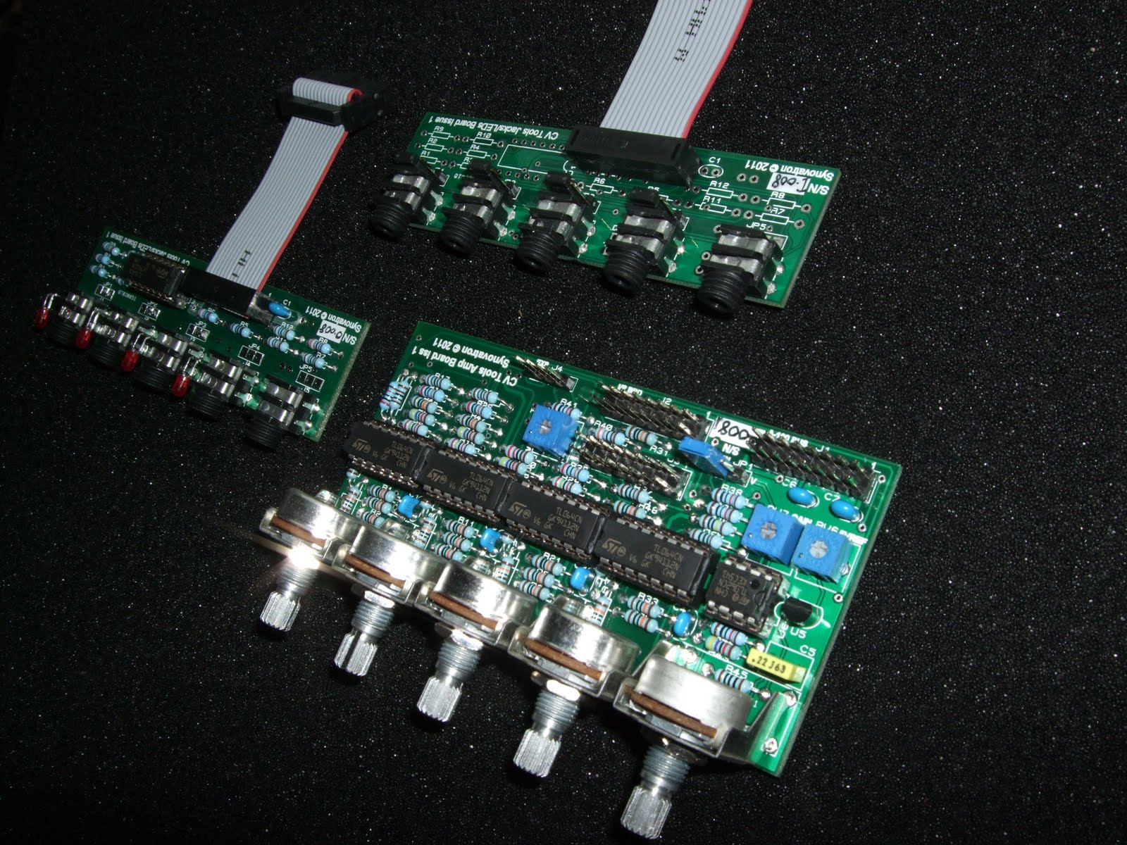 |
| All three fully built boards |
 |
| First modules off the production line after inspection and testing |
 |
| This is all the bits that make up one module - it's what you get in a kit |

To round off this project page here are a couple of videos that compare the ARP2600's Voltage Processor and CV Tools.
Best wishes
Tony
I've been following your progress on this project and it's been fascinating reading. Do you have an idea yet how much the finished CV Tools module will be, either as a kit or pre-built?
ReplyDeletenice one...i think i will buy a kit soon :-) nice job ..thx
ReplyDeleteThanks to Chris for the idea of bringing CV Tools out in kit-form as well and to Citric Acid for the nice comments
ReplyDelete